Be a fully automatic bicycle light without charging
Circuit diagram:
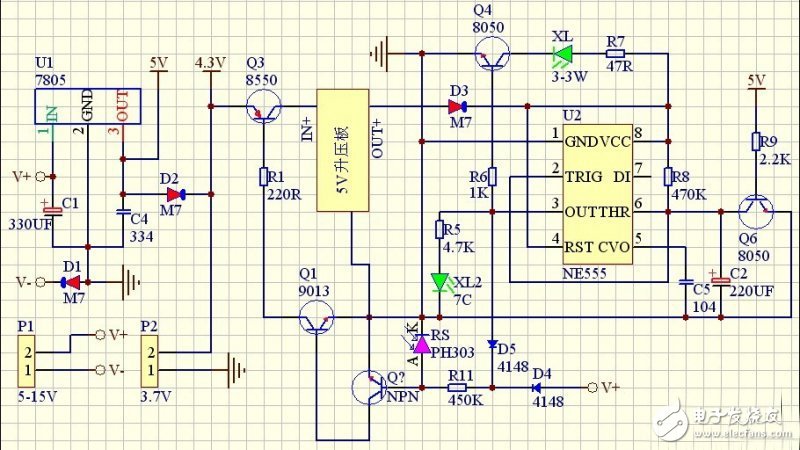
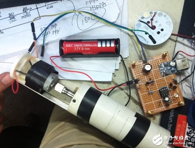
P1 connected to the generator (using 370 motor)
P2 is connected to the battery (preferably with a protected lithium battery battery such as a mobile phone battery)
XL for 3W piranha LED lights
XL2 is a 7-color LED light (5MM)
In normal use, in addition to the battery itself, the circuit basically consumes no electricity. When it is used, it will charge the battery. The 370 power generation current is small, and the output is about 300 to 500MA after the voltage regulation, so there is no fear of battery explosion. During the driving process of the bicycle, the LEDs use the electricity generated by the 370 motor. As long as the time for stopping the parking delay is too long, the battery can be used for a long time (usually 30 seconds to 1 minute or so should be enough). If the parking delay is on for a long time, it is another matter.
positive
Negative

Power generation with 370 motor: If you don't have a bicycle, use my hand drill instead.
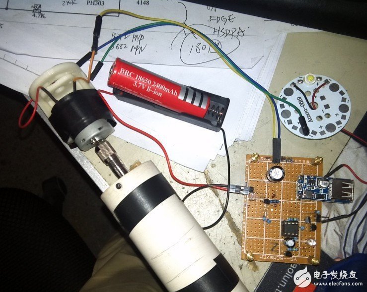
In the case of no battery installed, the motor turns on and the motor stops.
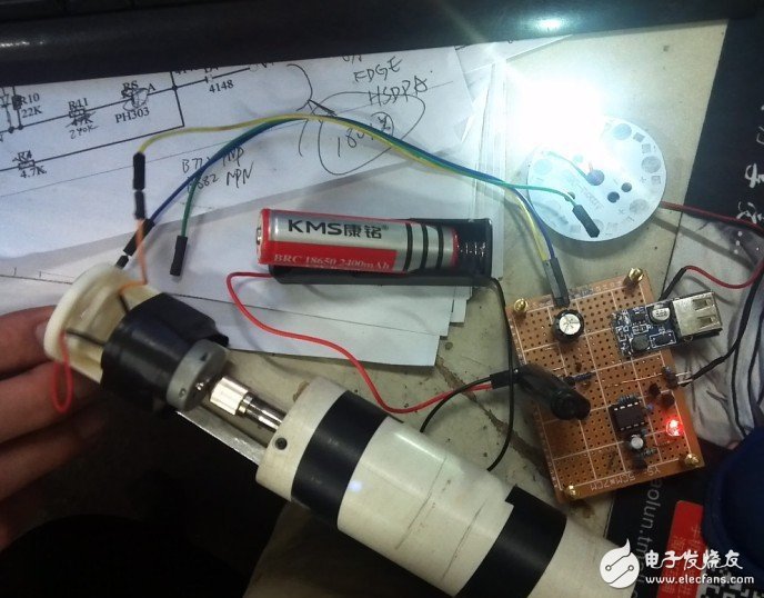
After the battery is installed: the motor turns on and the motor stops. The lamp delays for about 30 seconds.
If it is daylight, the light is not bright,
Circuit principle:
The 370 motor is used to generate electricity through the wheels; after passing through U1 (78M05), it outputs 5V voltage, and after D2 (4007), the voltage is about 4.3V;
Daytime: RS resistance is very small, Q3 is not conductive (adjusting R11 can adjust the critical state and sensitivity of Q1), the light will not light, then the battery will be charged;
At night: the light dims, the RS resistance becomes larger, when it is greater than a certain value (related to the resistance of R11), the Q3 base level has a low voltage, then Q3 is turned on, the 5V boost circuit starts to work, Q6 turns on, NE555 6 Foot level, output (3 feet output high level) LED light, 7 color LED light. When the 370 motor stops rotating (such as someone in front needs to stop the car) Q6 is cut off, C2 is charged, when the voltage of NE555 6 is greater than 2/3VCC (the charging process is a delay process, the time can be determined by adjusting the size of R8 and C2) The longer the RC is, the longer it takes. The 3 pin outputs a low level, and the LED light is off.
The copper base board is the most expensive one among the metal substrates, and the heat conduction effect is many times better than that of the aluminum substrate and the iron substrate. It is suitable for high-frequency circuits and regions with high and low temperature variations and the heat dissipation and architectural decoration industries of precision communication equipment.
Generally, the finishing include ENIG, immersion silver, LF HASL, OSP, etc. The copper substrate circuit layer is required to have a large current carrying capacity, so a thick copper foil should be used, and the thickness is generally 35 μm to 280 μm; the thermal conductive insulating layer is the core technology of the copper substrate, and the core thermal conductive component is aluminum oxide and silicon powder. It consists of a polymer filled with epoxy resin, low thermal resistance (0.15), excellent viscoelasticity, resistance to heat aging, and ability to withstand mechanical and thermal stresses.
Copper Base Pcb,Copper Circuit Board,Heavy Copper Pcb,Copper Clad Pcb
Chuangying Electronics Co.,Ltd , https://www.cwpcb.com