Radiation emission (RE) testing is mainly to measure the electromagnetic disturbance energy of the equipment under test. Due to the increasing development of electronic devices, the number of surrounding electronic devices is increasing, and the electromagnetic environment is becoming more and more crowded. The purpose of the RE test is to control the electromagnetic radiation of the device under test so that it does not interfere with surrounding electronic equipment.
Medical equipment can be classified into Class A and Class B equipment according to the use environment: Class A equipment refers to non-home equipment or equipment that is not directly connected to the residential low-voltage power supply network facilities; Class B equipment refers to household equipment and directly connected to the residential Equipment used in low voltage power supply network facilities.
For Class A equipment, the test for radiated emissions specified in CISPR11 can be performed either at the test site or at the site.
This is explained in CISPR11: “Due to the size, structural complexity and operating conditions of the equipment under test, some engineering medical equipment can only be tested by field to determine whether it meets the radiation emission limits specified in this standard. "MRI and DR products are basically Class A devices, so the test of their radiation emissions can be carried out in the form of field tests.
Test limit
In addition to the division of Class A and Class B, engineering and medical equipment can be divided into 1 group and 2 groups according to the purpose of RF energy. The definitions of Group 1 and Group 2 equipment are as follows:
A group of engineering equipment: All medical equipment that intentionally produces and/or uses conductively coupled RF energy to meet its own functional needs.
2 sets of engineering equipment: including electrical discharge machining (EDM) and arc welding equipment, and all engineering equipment that intentionally produces and/or uses electromagnetic radiation RF energy for material processing. Most types of devices and systems generate or use RF energy only for their internal functional needs and therefore belong to Group 1. Such as ECG and magnetocardiography equipment and systems, EEG and magnetoencephalography equipment and systems, and so on. Other devices and systems that expect to deliver energy to patients in non-RF electromagnetic form are also part of a group of devices, such as medical imaging devices and systems - X-ray diagnostic systems, CT systems, nuclear medicine systems, ultrasound diagnostic systems, etc.; Systems - X-ray therapy systems, ultrasound therapy systems, infusion pumps, ventilators, etc.; monitoring equipment and systems - impedance plethysmographs, pulse oximeters, etc. Only a few devices and systems are applying RF energy to the material (the medical device is for the patient) and belong to 2 groups of devices. Commonly used in 2 groups of equipment are: magnetic resonance imaging system, diathermy equipment (short wave, ultrashort wave, microwave therapy equipment), hyperthermia equipment and high frequency surgery system.
The emission limits for Group 1 and Group 2 Class A equipment are shown in Tables 1 and 2, and the limits for the two groups are different.
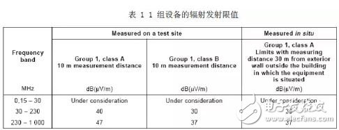
For a group of Class A equipment, the field test limits are the same as those in Table 1. In the case of a group A and B equipment that is to be permanently installed in an X-ray shielding site, the electromagnetic radiation emission limit is allowed to increase by 12 dB when measured at the test site.
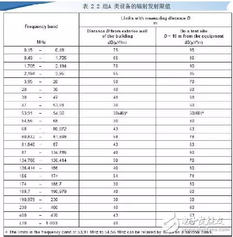
For the two groups of Class A equipment tested in the field, as long as the test distance D in Table 2 is within the perimeter of the jurisdiction, the test distance is calculated from the building exterior wall where the equipment under test is installed, D = (30 + x / a) ( The unit is m, m) or D=100m, whichever is smaller. When the calculated distance D exceeds the perimeter of the jurisdiction, then D=x or 30m, whichever is greater.
x is the closest distance in each measurement direction between the building's exterior wall where the device under test is installed and the perimeter of the user's jurisdiction;
a=2.5 (frequency below 1MHz)
a=4.5 (frequency is greater than or equal to 1MHz)
In order to protect the dedicated aviation business in a particular area, the relevant national authorities may require that the 30m distance be a defined limit.
2. Environmental requirements
In the field test, because it is not a special shielding test field, it will receive various environmental interferences, such as mobile communication signals, broadcast signals, etc. These environmental noise effects should be considered in the test. The test site should be able to ensure that the emissions of the equipment under test are distinguished from environmental noise.
To distinguish between ambient noise and the emissions of the device under test, the ambient noise level should be measured prior to testing. Before testing, place the antenna and receiver in the normal test setup, turn off the device under test, and measure the level of noise in the environment.
Test results should be as close as possible to ensure that the ambient level is at least 6 dB below the specified limit of the EUT for measurement. Therefore, when testing, you should try to close the surrounding electronic equipment and other equipment that may affect the radiation characteristics to ensure a relatively pure test environment.
Due to the site limitations of the field test, sometimes the interference cannot be eliminated artificially and the 6dB margin cannot be met. In this case, the following solutions are given in CISPR11:
1. When the ambient level plus the emission of the device under test does not exceed the specified limit, there is no need to reduce the environmental level to less than 6 dB of the specified limit. In this case, the device under test can be considered. The specified limits have been met.
2. If field strength measurement cannot be performed at a specified distance due to ambient noise level or other reasons, it can be measured at the distance of follow-up. The distance and test should be recorded in the test report at this time. In order to determine eligibility or not, the measurement data should be normalized to the specified distance by an inverse ratio factor of 20 dB per 10 times distance. When measuring large test pieces at a distance of 3 m, pay attention to the effect of near-field effect when the frequency is close to 30 MHz.
3 test layout
3.1 Antenna layout
According to the requirements of cispr11 clause9: “The equipment that is not measured in the radiation test site can be measured after installation in the user's jurisdiction. It should be measured outside the outer wall of the building where the equipment is installed, using the test distance specified in Section 5. Taking the DR product as an example, the DR product is placed in an X-ray shielding room and the antenna is tested outside the exterior wall.
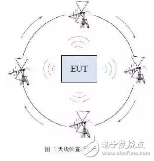
The antenna used in the field measurement is the same as the antenna used in the test field. Other types of antennas can be used if the difference between the measurement result and the balanced dipole antenna measurement is within 2 dB. The 3m method is used for testing, but the antenna measured in the field no longer rises and falls within the range of 1~4m, but the center of the antenna is fixed at a height of 2.0m±2.0m above the ground. The position of the antenna is selected to be measured in at least four directions orthogonal to the shielded chamber, as shown in Figure 1. In addition to these four points, test points should be selected as much as possible, centered on the shielded room, where practical conditions permit, and should be measured in any direction that may have a detrimental effect on the radio system.
3.2 Equipment layout
When measuring radiated emissions, the settings of the device should be adjusted as much as possible to obtain the maximum level of disturbance level, depending on the inherent maneuverability of each particular device. In the field test, for the specific equipment, it is necessary to take into account the change of the cable position and the different operation within the equipment, and the extent to which the equipment can move in the house on site. The layout of the equipment to be tested should be accurate. Recorded in the test report.
The length and type of interconnecting cable between devices should be consistent with the specifications in the individual device technical requirements. If the cable length can be changed, the choice should be made to maximize when making field strength measurements. If shielded or special cables are to be used in the test, they should be clearly stated in the instruction manual. Where there are multiple interfaces of the same type, if the number of cables is added and does not significantly affect the measurement results, just use one cable to connect to one of the interfaces.
Any set of measurements should be fully enriched with the cable and device location to allow for this measurement to be reproduced. If there are conditions of use, provisions should be made and incorporated into the instruction manual for use. If a device can perform several functions separately, the device should be tested when performing each function. For systems with several different types of equipment, at least one of each type of equipment should be included in the evaluation. If the system contains several identical devices, just evaluate one of the devices. If the initial evaluation meets the requirements, no further evaluation is required. When evaluating devices that are connected to other devices to form a system, other devices or simulators can be used to evaluate the entire system. Both methods of evaluation of the equipment under test shall ensure that other parts of the system or the simulator affect the requirements of the standard pair and the ambient noise level. Any simulator that replaces the actual equipment should be able to fully represent the electrical and mechanical characteristics of the interface interface, especially the RF signal and RF impedance, cable layout and its model number. Taking the DR product as an example, in the field test, the device is basically fixed after installation and will not move any more, so the device itself does not need to be moved. The DR interconnect cable is relatively long. Under the premise of ensuring the complete assembly of the cable, the test should be carried out in different ways to achieve the maximum disturbance. Some components of the DR product have mechanical motion, exposure and other functions. They should be tested under different functional conditions during the test, and the maximum value of the radiation emission is taken as the final test result.
3.3 test steps
According to the above analysis, during the field test, the measurement has been carried out according to the following procedure:
1. Arrange the equipment under test according to the typical installation requirements of the client. The wire shall comply with the length and model specified in the specification;
2. Place the antenna and receiver at 3m from the outer wall of the EUT (test equipment), and adjust the antenna center to a height of 2m from the ground;
3. Turn off the device under test and test the ambient noise level.
4. Turn on the device under test, adjust the wiring mode, perform different functions, and find the maximum radiation mode.
5. Rotate the antenna to test horizontal and vertical radiated disturbances;
6. Move the antenna around the device under test, and select as many test points as possible to measure;
7. Select the highest radiation level as the measurement result;
8. Turn off the device.
We are committed to providing safe, high-end, energy-saving and efficient UV Disinfection Lamp products. Wholesale cold cathode Ultraviolet Lamp, hot cathode ultraviolet lamp, E-27, E-T5, UV3 ultraviolet lamp and other high quality products. We have perfect after-sales service and technical support. We look forward to your cooperation.
Uv Lighting,Uv Lights In Air Handling Units,Ultraviolet Led,Uv Disinfection Light
t-smartlight , https://www.t-smartlight.com