In practice, the signal is often wireless bandwidth. How to ensure limited bandwidth? Therefore, we need to add a low-pass filter at the input of the analog signal to make the signal into a limited bandwidth, and then use the highest signal frequency of 2.5~3 times for sampling. About this we will see the analog to digital conversion process below.
Come and see, a few points:
Limited bandwidth (band-limited)
The sampling frequency is greater than 2 times the maximum frequency of the signal, and the original signal can be recovered without distortion.
In practice, the signal is often wireless bandwidth. How to ensure limited bandwidth? Therefore, we need to add a low-pass filter at the input of the analog signal to make the signal into a limited bandwidth, and then use the highest signal frequency of 2.5~3 times for sampling. About this we will see the analog to digital conversion process below.
Although it can't be less than or equal to 2 times, but choosing 2 times is not very good. In theory, the higher the sampling frequency is selected, the more the original signal can be recovered without distortion, but the higher the sampling frequency, the processing of the back-end digital system. The higher the speed and storage requirements, so choose a compromise value.
If the window selection in the back-end digital signal processing is too narrow, the sampling rate is too high, and it is difficult to accommodate even one cycle of the signal in one window, which makes the signal unrecognizable in some respects. For example, the window size of digital signal processing is 1024 points, and the sampling rate is 50KHz. The window can accommodate a maximum of 1024*(1/50KHz)=20.48ms signal length. If one period of the signal is 30ms" 20.48ms, this makes The processing window of the digital signal cannot accommodate a periodic signal. The solution is to reduce the sampling rate or increase the window length if the requirements are met.
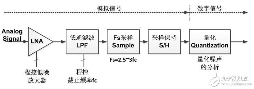
1 analog to digital conversion
I remember once I participated in the internship written test of the Institute of Computing Technology of the Chinese Academy of Sciences. There is such a question: What are the two steps to be taken to convert an analog signal to a digital signal? Fortunately, I was prepared and immediately filled in the sampling and quantification. Let's take a closer look at the two processes below, but before we analyze, let's give a flow diagram of the whole process. You can think about why you need each module first.
Programmable amplifier
The actual analog signals are collected by the sensor. Those who have done the MCU should be familiar with the DS18B20 temperature sensor. Sorry, it is a digital sensor. That is to say, when the sensor is used, the AD conversion is also placed in the sensor. . But this is not a common situation, because the amount of temperature is the easiest to measure in analog signals, and most sensors do not integrate AD conversion processes, such as most acceleration sensors, vibration sensors, sound sensors, electronic compasses, Even some GPS (don't worry, GPS is a kind of sensor), etc., are analog output. And because of the physical production, the electrical signal returned by the sensor is very small, usually a few mV (if it is current, usually a few mA), such a weak signal, if transmitted through the wire or cable is easily annihilated in the noise. Therefore, we often see that the output line of the analog sensor will use a plastic wire, called the shield wire (pictured).

Shielded wires only guarantee minimal interference before the signal is transmitted to the system, but the signal still has to be processed for use in digital systems. At the input of an analog signal (especially a high-frequency signal), the signal is first amplified using a low-noise amplifier. This amplifier has special requirements and must be low-noise. We already know that the analog signal is already very weak, if the amplifier is still There is a certain amount of noise, and the signal amplified after the noise is superimposed may no longer be the original signal. Since low noise is mentioned, how is low noise measured? This can be determined by the amplifier noise figure (NF).
The noise figure is defined as the signal-to-noise ratio of the amplifier's input and output signals. Its physical meaning is: after the signal passes through the amplifier, the signal-to-noise ratio is deteriorated due to the noise generated by the amplifier; the multiple of the signal-to-noise ratio is the noise figure. The noise figure is usually expressed in dB.
In practice, in addition to considering the low noise figure, consider the bandwidth and frequency range of the amplifier and the most important amplification gain. Since the strength of the input signal may vary from time to time, the program-controlled (programmed) amplification gain ensures that the signal can reach fullness without saturation (it is still difficult to do this in practice).
Xinxiang Mina Import & Export Co., Ltd. , https://www.mina-motor.cn