As an analysis and design tool, finite element method (FEM) has been widely used in many electronic engineering fields such as antenna, microwave and signal integrity. The FEM solver has several significant advantages over other numerical methods such as MoM and FDTD. These advantages include the ability to handle complex non-uniform and anisotropic materials, the ability to accurately depict complex geometries with tetrahedral elements, the ability to achieve accuracy using high-order basis functions, and excitations with multiple ports and incident waves. Utilizing these functional advantages, FEM is able to model the waveguide structure with extremely high accuracy.
However, for open space problems (such as when the antenna radiates into open space), the FEM solver needs to set the radiated boundary condition (RBC) on the artificially truncated boundary surface to cut the infinite domain into a finite field. Two widely used RBCs include first-order absorbing boundary conditions (ABC) and ideal matching layers (PML), which typically provide the best accuracy. Both methods preserve the sparsity of the FEM system matrix, but only for raised radiating surfaces. Both are approximate methods, all of which have accuracy problems, such as non-physical false reflections from the radiating surface. This problem can be solved by increasing the spacing between the RBC and the radiating structure to reduce the reflection to a negligible level.
On the other hand, the integral equation (IE) method, such as MoM, is well suited for modeling structures located in homogeneous or infinite media. The analysis kernel uses the Green's function to apply Sommerfeld radiation conditions at infinity. Therefore, whether it is from memory usage or CPU time occupation, the IE solver is undoubtedly a better choice for multiple spatially separated, unconnected homogeneous structures, because it does not need to Detailed modeling of the space between targets.
As early as 1990, Yuan has successfully implemented the hybrid algorithm of FEM solver and IE solver. This method is now commonly known as hybrid finite element boundary integral method (FEBI). This method integrates the boundary: the MoM solution of the Sommerfeld radiation condition is used as the truncation boundary of the FEM solution, so that the far-field radiation conditions can be theoretically accurately processed. This leads to a series of interesting features, such as a fully conformal radiating surface that can be used in any shape that is close to the radiator.
This article introduces a new FEBI solver from ANSYS in HFSS. The solver is powered by recent advances in regional decomposition methods. In the existing FEBI method, the infinite unknown domain is divided into two non-overlapping domains: a bounded FEM domain and an unbounded homogeneous outer domain. The coupling between the two domains is considered by appropriate boundary conditions at their interfaces.
Domain decomposition based FEBI solver
The FEBI solver first splits the original target domain Ω into two non-overlapping subfields Ω1 and Ω2, as shown in Figure 1.
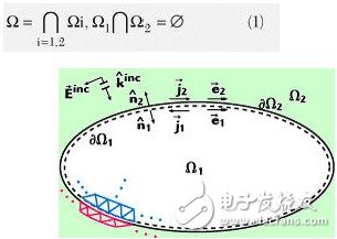
Figure 1: Decomposition of the target domain into a FEM domain and an IE domain.
The common interface between Ω1 and Ω2 is expressed as δΩ1 in the FEM domain and δΩ2 in the IE domain. This distinction is necessary because the existing equation allows for non-conformal coupling between the two domains. That is to say, the meshing, basis function and basis function order, matrix establishment and solution process of each domain can be processed separately. For a robust FEBI solver, it is important to be able to handle the different basis functions of each domain in a modular way, as higher-order IE solvers are still in development.
According to the above domain decomposition situation, the following final system matrix can be written:
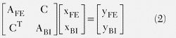
Here, AFE and ABI represent system matrices of FEM domain and BI domain, respectively. C is the coupling matrix between the two domains. This coupling is very sparse because it is coupled by current and magnetic current on the interface. The solution of Equation 2 can be obtained by iteratively splitting the following formula.

Then use the iterative method to find:

The advantages of the domain decomposition method can be clearly seen from Equation 4. The FEM domain and the BI domain are decoupled, so parallelization is easy. As already mentioned above, BI can be used as an accurate truncation boundary in FEM. Due to the modular nature of this implementation, the hybrid solution of the advanced FEM solver and IE solver can be easily implemented.
application
In this section, we highlight two examples of using this hybrid approach to highlight the advantages of FEBI. As mentioned earlier, the first-order ABC can be used for a sufficiently large bounded conformal space, but this space cannot have depressions. On the other hand, PML can close the distance from the model, but is most suitable for the bounded area of ​​the cuboid. For hybrid FEBI technology, the constraints of current and magnetic current on the boundary can be accurately calculated without considering the constraints of these shapes and sizes. From the test of this new boundary, it can be seen that when the pitch is λ0/10, the optimal balance of speed and solution scale can be achieved. 5. Here, λ0 is the wavelength in open space. In addition, the FEBI boundary can be fully conformal, including concave areas. In addition, each part of the model can be independently closed into separate domains, each with a BI boundary. By using highly conformal and spatially separated regions, the range of the finite element solution domain can be greatly reduced, enabling efficient simulation. To prove this, two examples are presented below, one using independent spaces and one using highly conformal boundary surfaces.
The first example uses a dielectric lens that is fully compliant with the textbook. 6. The lens and its feed horn are shown in Figure 2. The lens focuses the electromagnetic field from the source antenna directly in front. The simulated lens uses a rectangular parallelepiped waveguide as the feed source with εr=2.56 and a front diameter of 4.4λ0. Then the mixed FEBI method is used to model the separation domain of the system. The feed horn and the surrounding cuboid space serve as a domain around the lens. The conical region serves as another domain, and the cross-section of each separation space adopts a BI boundary.
For the sake of comparison, PML was used to model the antenna system. In order to obtain an accurate answer, a larger cuboid air box was used to wrap the entire model and a sufficient distance from the radiator to ensure the result. accurate. Compared to PML simulation, the smaller space used by the FEBI model can reduce memory usage by a factor of 10. The figure also shows the shadow maps of the electric fields calculated by the two simulations. As shown, although the separation space used by the FEBI simulation is small, the electromagnetic fields inside and outside the lens and the horn are accurately calculated and consistent with the results of the PML calculation. The reflection coefficient (Г) of the horn increases as the distance from the lens decreases. Both simulations show that Г has the same increase of 1.8 dB when comparing the speaker port reflections before and after the addition of the lens. Figure 3 is a front view of the antenna system calculated by the two methods. It again shows a high degree of agreement between FEBI and PML. Figures 2 and 3 illustrate that FEBI has considerable accuracy in using the separation space to determine the characteristics of the antenna system.
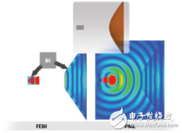
Figure 2: Dielectric lens with a rectangular horn feed.
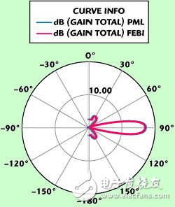
Figure 3: Radiation characteristics of the lens.
The second example examines a set of antenna arrays mounted on a complex platform (Figure 4). It is a 7-element array of helical antennas mounted on a satellite platform. The length between the two ends of the satellite is 18 feet and the antenna operates at 3.5 GHz. Since this is a large model, domain decomposition (DDM) is still used to split the FEM domain into multiple smaller domains. 7 The antenna system of this integrated carrier platform was previously simulated using standard ABC, using a large closed cuboid space. The volume of the closed space of the model is approximately 21000λ, and DDM decomposes the solution range into 34 domains. The total storage required for the simulation is 210GB RAM.
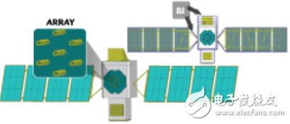
Figure 4: Helical antenna array mounted on a satellite.
The FEBI simulation uses a fully conformal space as shown. The closed space volume drops to 1200λ3. Since the target space is reduced, only DDM needs to be applied on 12 domains, and emulation is as long as 21 GB of RAM is sufficient. The storage size required for FEBI simulation is significantly reduced compared to using standard RBC solvers. Figure 5 shows the radiation characteristics of all antenna elements for both simulations with equal amplitude and phase excitation, and the two characteristics are perfectly matched. The three-dimensional polar coordinate pattern obtained by FEBI simulation of an equal-excitation antenna array located on a satellite is shown in Fig. 6. Based on this example, it can be seen that by combining FEBI with a highly conformal bounded domain, simulation of large complex antenna systems can be performed on a single desktop computer.
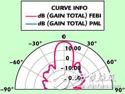
Figure 5: Radiation characteristics of an antenna array mounted on a satellite.
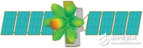
Figure 6: Three-dimensional polarization diagram of the radiated electromagnetic field under the same excitation of a 7-element array.
Summary of this article
Hybrid FEBI is a powerful new addition to the HFSS FEM solver. Design engineers can use this new technology to combine the benefits of FEM simulation with the efficiency and accuracy of the IE solver on open boundary issues. This method can achieve considerable accuracy for conformal regions, concave spaces, and independent spaces, allowing users to narrow the scope of the FEM solution domain, thereby significantly reducing solution time and reducing the memory required for solving.
Digital Signage Player,Electronic Signage,Signage For Hotels,Commercial Digital Signage Displays
Guangdong Elieken Electronic Technology Co.,Ltd. , https://www.elieken.com