Many aerospace and defense electronic systems in the field of satellite communications, radar and signal intelligence (SIGINT) have long required the use of some or all of the X and Ku bands. As these applications move to more portable platforms such as unmanned aerial vehicles (UAVs) and handheld radios, the development of new small-sized, low-power radio designs that work in the X and Ku bands while still maintaining extremely high performance levels becomes It is vital. This article describes a new high-IF architecture that significantly reduces the size, weight, power, and cost of receivers and transmitters without compromising system specifications. The resulting platform is also more modular, flexible, and software-defined than existing radio designs.
Introduction
In recent years, the power to drive RF systems to achieve wider bandwidth, higher performance, lower power consumption, while increasing the frequency range and reducing the size is becoming more and more powerful. This trend has become the driving force for technological advancement, and the integration of RF devices far exceeds what has been seen in the past. There are many factors driving this trend.
In order to transmit and receive several terabytes of data collected each day, the satellite communication system has reached a data rate requirement of 4 Gbps. This requirement pushes the system's operating frequency to the Ku and Ka bands because it is easier to achieve wider bandwidth and higher data rates at these frequencies. This will inevitably lead to higher channel densities and wider bandwidth per channel.
In the field of signal intelligence, performance requirements are also increasing. The scanning rate of such systems is getting higher and higher, requiring the system to have a fast tuning PLL and wide bandwidth coverage. The need for smaller, lighter, lower power (SWaP) and more integrated systems stems from the industry's desire to operate handheld devices in the field and to increase the channel density of large fixed-location systems.
The development of phased arrays also benefits from the increased integration of single-chip RF systems. The integration allows the transceiver to be smaller and smaller, so that each antenna element can have its own transceiver, which in turn causes the analog beamforming to transform into a digital beam. With digital beamforming, a single array can track multiple beams simultaneously. Phased array systems are used in a wide range of applications, including weather radar and directional communications. As the low frequency signal environment becomes more and more congested, many applications inevitably require increased frequency.
This article describes how to address these challenges with a highly integrated architecture that uses the AD9371 transceiver as an IF receiver and transmitter, allowing the entire IF stage and its associated components to be removed from the system. This article compares the traditional system with the proposed architecture and illustrates how this architecture can be implemented through a typical design flow. In particular, some advanced frequency planning can be achieved using an integrated transceiver, which is not possible with standard superheterodyne transceivers.
Superheterodyne architecture overview
The superheterodyne architecture has become the preferred architecture for many years due to its high performance. The superheterodyne receiver architecture typically includes one or two mixing stages, and the mixing stage is fed into an analog-to-digital converter (ADC). A typical superheterodyne transceiver architecture is shown in Figure 1.
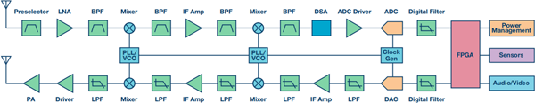
Figure 1. Traditional X and Ku-band superheterodyne receive and transmit signal chains
The first conversion stage upconverts or downconverts the input RF frequency to the out-of-band spectrum. The frequency of the first IF (intermediate frequency) depends on the frequency and spur plan, the mixer performance, and the filter used by the RF front end. The first IF is then downconverted to a lower frequency that the ADC can digitize. Although the ADC has made great progress in handling higher bandwidth, the upper limit of the frequency is currently around 2 GHz for optimal performance. Higher input frequencies must account for performance loss, and higher input frequencies require higher clock rates, which can result in increased power consumption.
In addition to the mixer, there are filters, amplifiers and step attenuators. Filtering is used to suppress unwanted out-of-band (OOB) signals. Without suppression, these signals can cause spurs on the target signal, making the target signal difficult or impossible to demodulate. The amplifier sets the noise figure and gain of the system, providing a high enough sensitivity to receive small signals while not too high for the ADC to be oversaturated.
It is also important to note that this architecture often requires the use of surface acoustic wave (SAW) filters to meet the stringent anti-aliasing filter requirements of the ADC. The SAW filter provides sharp roll-off performance to meet these requirements, but it also introduces significant delay and ripple.
Figure 2 shows an example of frequency planning for an X-band superheterodyne receiver. The receiver expects to receive signals between 8 GHz and 12 GHz with a bandwidth of 200 MHz. The target spectrum is mixed with a tunable local oscillator (LO) to produce a 5.4 GHz IF. The 5.4 GHz IF is then mixed with the 5 GHz LO to produce the final 400 MHz IF. The final IF range is 300 MHz to 500 MHz, which is the frequency range in which many ADCs can perform well.
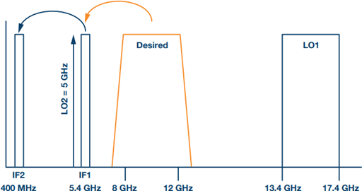
Figure 2. Example of an X-band receiver frequency plan
Important characteristics of the receiver
In addition to well-known gain, noise figure, and third-order intercept point characteristics, other typical characteristics that affect receiver architecture frequency planning include image rejection, IF rejection, spontaneous spurs, and LO radiation.
• Image spurs—RFs outside the target band that mix with the LO to produce IF interference. • IF spur—A signal of the IF frequency that is sneaked through the filter before the mixer and is shown as IF interference. LO radiation - RF leakage from the LO to the input connector of the receiver chain. LO radiation is detectable and can be detected even in only the received operating mode (see Figure 3).
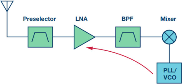
Figure 3. LO radiation leakage returns through the front end
• Spontaneous spurs—IF spurs caused by the internal clock or local oscillator mixing of the receiver.
The image rejection feature applies to both the first and second mixing stages. In typical applications in the X and Ku bands, the center frequency of the first mixing stage can be a high IF in the 5 GHz to 10 GHz range. A high IF is required here because the image frequency is Ftune + 2 × IF, as shown in Figure 4. The higher the IF, the farther the image band is. This image band must be suppressed before it reaches the first mixer, otherwise the out-of-band energy in this range will appear as a spur in the first IF. This is one of the main reasons why two mixing stages are usually used. If there is only one mixer and the IF is hundreds of MHz, it will be difficult to suppress the image frequency in the receiver front end.
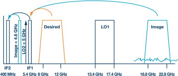
Figure 4. Mixing into the IF image
When the first IF is downconverted to the second IF, the second mixer also has an image band. The frequency of the second IF is low (several hundred MHz to 2 GHz), so the filtering requirements of the first IF filter may vary from case to case. For a typical application where the second IF is a few hundred MHz, the filtering of the high frequency first IF can be very difficult and requires a large custom filter. This is often the most difficult filter to design in a system because the frequency is high and the rejection requirements are usually narrow.
In addition to image rejection, the LO power level returned from the mixer to the receive input connector must be strongly filtered out. This ensures that the user cannot be detected due to radiated power. To do this, the LO should be kept away from the RF passband to ensure adequate filtering.
High IF Architecture Overview
The latest integrated transceiver products include the AD9371, a 300 MHz to 6 GHz direct conversion transceiver with two receive channels and two transmit channels. The receive and transmit bandwidths can be adjusted from 8 MHz to 100 MHz and the operating mode can be configured for either Frequency Division Duplex (FDD) or Time Division Duplex (TDD). The device is available in a 12 mm2 package and consumes approximately 3 W in TDD mode and approximately 5 W in FDD mode. Thanks to the advantages of Quadrature Error Correction (QEC) calibration, it achieves image rejection from 75 dB to 80 dB.
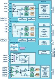
Figure 5. Functional Block Diagram of the AD9371 Direct Conversion Transceiver
The performance advancement of integrated transceiver ICs opens up new possibilities. The AD9371 integrates a second mixer, a second IF filter and amplification, a variable attenuation ADC, and digital filtering and decimation of the signal chain. In this architecture, the AD9371 (with a tuning range of 300 MHz to 6 GHz) can be tuned to frequencies between 3 GHz and 6 GHz to directly receive the first IF (see Figure 6). With a gain of 16 dB, an NF of 19 dB, and an OIP3 of 40 dBm at 5.5 GHz, the AD9371 is an ideal IF receiver.
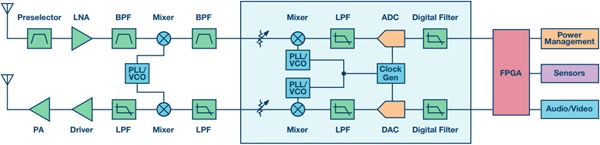
Figure 6. X or Ku-band TRx, AD9371 used as an IF receiver
By using the integrated transceiver as an IF receiver, there is no longer a need to worry about mirroring through the second mixer as with a superheterodyne receiver, which can greatly reduce the filtering requirements of the first IF band. However, in order to eliminate the second-order effects in the transceiver, some filtering is still required. The first IF band should now provide filtering at twice the first IF frequency to eliminate such effects, which is much easier than filtering out the second image and the second LO, which may be close to hundreds of MHz. Typically, such filtering requirements are met with low cost, small LTCC filter products.
This design also gives the system a high degree of flexibility and can be easily reused for different applications. One of the manifestations of flexibility is the choice of IF frequency. The general rule of thumb for IF selection is to make it 1 GHz to 2 GHz higher than the target spectrum bandwidth of the front-end filtering. For example, if a designer needs a 4 GHz spectral bandwidth (17 GHz to 21 GHz) through a front-end filter, the IF can be at 5 GHz (1 GHz above the target bandwidth of 4 GHz). This helps the front end achieve filtering. If only 2 GHz bandwidth is required, a 3 GHz IF can be used. In addition, the AD9371 has software-defined features that make it easy to change the IF at any time, making it ideal for cognitive radio applications that need to avoid blocking signals. The bandwidth of the AD9371 can also be easily adjusted from 8 MHz to 100 MHz to avoid interference near the target signal.
The high integration of the high-IF architecture makes the final receiver signal chain occupy only about 50% of the equivalent superheterodyne architecture, while reducing power consumption by 30%. In addition, high IF architecture receivers are more flexible than superheterodyne architectures. This architecture is the gospel of the low SWaP market that requires small size and high performance.
High IF architecture receiver frequency planning
One of the advantages of the high IF architecture is the ability to tune the IF. This ability is especially useful when trying to create a frequency plan that avoids interference spurs. Interference spurs are caused when the received signal is mixed with the LO in the mixer and produces an m × n spur of the target tone in the non-IF band.
The mixer produces an output signal and spurs according to the formula m × RF ±n × LO, where m and n are integers. The m × n spurs generated by the received signal may fall in the IF band; in some cases, the target tone will cause crossover spurs at a particular frequency.
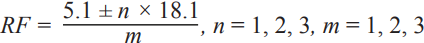
For example, if you observe a system designed to receive a 12 GHz to 16 GHz signal with an IF of 5.1 GHz, as shown in Figure 7, the m × n image frequency that causes the in-band spurs can be determined according to the following equation:
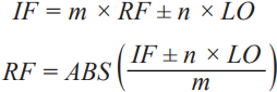
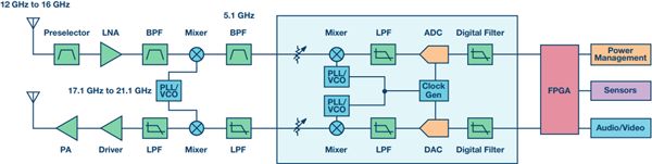
Figure 7. 12 GHz to 16 GHz Rx Tx high IF architecture
In this equation, RF is the RF frequency at the input of the mixer, which causes a signal tone to fall in the IF. As an example, assume that the receiver is tuned to 13 GHz, which means the LO frequency is 18.1 GHz (5.1 GHz + 13 GHz). Substituting these values ​​into the above equation and allowing m and n to vary from 0 to 3 gives the following RF formula:
The results are shown in the table below.
Table 1. M × N spurious tables for 18.1 GHz LO
| m | n | RFsum (GHz) | RFdif (GHz) |
| 1 | 1 | 23.2 | 13 |
| 1 | 2 | 41.3 | 31.1 |
| 1 | 3 | 59.4 | 49.2 |
| 2 | 1 | 11.6 | 6.5 |
| 2 | 2 | 20.65 | 15.55 |
| 2 | 3 | 29.7 | 24.6 |
| 3 | 1 | 7.733 | 4.333 |
| 3 | 2 | 13.767 | 10.367 |
| 3 | 3 | 19.8 | 16.4 |
The first line in the table (yellow highlight) shows the desired 13 GHz signal, which is the result of 1 ×1 in the mixer. Other highlighting units display in-band frequencies that may be problematic, which may appear as in-band spurs. For example, the 15.55 GHz signal is in the target range of 12 GHz to 16 GHz. A 15.55 GHz tone is mixed with the LO at the input to produce a 5.1 GHz tone (18.1 × 2–15.55 × 2 = 5.1 GHz). Other unlit lines can also cause problems, but because they are out of band, they can be filtered out by the input bandpass filter.
The level of spurs depends on several factors. The main factor is the performance of the mixer. The mixer is fundamentally a nonlinear device that generates many harmonics inside. The output spurious level can be determined based on the matching accuracy of the internal diode of the mixer and the optimization of the mixer's spurious performance. The data sheet usually provides a mixer spur chart that can help determine the level of spurs. The example shown in Table 2 is the spurious level table of the mixer HMC773ALC3B. This table gives the dBc level of spurs relative to the 1 × 1 target tone.
Table 2. HMC773ALC3B Mixer Spurious Table
| n ×LO | |||||||
| 0 | 1 | 2 | 3 | 4 | 5 | ||
| m ×RF | 0 | - | 14.2 | 35 | 32.1 | 50.3 | 61.4 |
| 1 | –1.9 | - | 17.7 | 31.1 | 32.8 | 61.2 | |
| 2 | 83 | 55.3 | 60 | 59.6 | 6 73.7 | 87.9 | |
| 3 | 82.6 | 86.1 | 68 | 68.5 | 61.9 | 85.9 | |
| 4 | 76 | 86.7 | 82.1 | 77.4 | 74.9 | 75.8 | |
| 5 | 69.3 | 74.7 | 85.3 | 87 | 85.1 | 62 |
Using this spurious table and extending the analysis done in Table 1, we can fully understand which m × n mirror tones can interfere with the receiver and what its level is. A spreadsheet can be generated with an output similar to that shown in Figure 8.

Figure 8. m × n mirroring of 12 GHz to 16 GHz Rx
The blue portion in this figure represents the required bandwidth. Line segments represent different m × n images and their levels. It is easy to know from this diagram what kind of filtering requirements must be met before the mixer can eliminate interference. In this example, there are multiple image spurs that fall within the band and cannot be filtered out. The following section shows how to take advantage of the flexibility of the high-IF architecture to circumvent some of the spurs that are not possible with superheterodyne architectures.
Avoid interference in receive mode
Figure 9 shows a similar frequency plan with a range of 8 GHz to 12 GHz and a default IF of 5.1 GHz. This figure is another view of the mixer spurs showing the relationship between the center tuning frequency and the m × n image frequency, rather than the spurious level shown previously. The 1:1 thick diagonal in this figure represents the desired 1 × 1 spur. The other lines on the graph represent m × n mirrors. The left side of this figure represents the part of the IF tuning that is not flexible. In this case, the IF is fixed at 5.1 GHz. At a tuning frequency of 10.2 GHz, the 2 × 1 image spurs cross the target signal. This means that if you tune to 10.2 GHz, it is likely that nearby signals will block the reception of the target signal. The right side shows how to solve this problem with flexible IF tuning. In this case, the IF switches from 5.1 GHz to 4.1 GHz around 9.2 GHz, preventing crossover spurs from occurring.
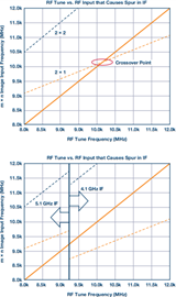
Figure 9. m × n crossover spurs without IF flexibility (top), avoiding crossovers with IF tuning (bottom)
This is just a simple example of how the high-IF architecture avoids blocking signals. When combining intelligent algorithms to determine interference and calculate new possible IF frequencies, there are many possible ways to construct a receiver that can flexibly adapt to any spectrum environment. This is as simple as determining the appropriate IF for a given range (usually 3 GHz to 6 GHz) and then recalculating and setting the LO based on that frequency.
High IF architecture transmitter frequency planning
As with the receive frequency plan, the flexibility of the high IF architecture can also be utilized to improve the spurious performance of the transmitter. For the receiver, the frequency components are sometimes unpredictable. But for the transmitter, the spurs at the output are easier to predict. This RF component can be predicted using the following formula:

Among them, the IF is predetermined by the AD9371 tuning frequency, and the LO is determined by the required output frequency.
Like the receiving channel, the transmitting side can also generate a mixer chart. An example is shown in Figure 10. In this figure, the maximum spurs are the mirror and LO frequencies, which can be reduced to the desired level using a bandpass filter after the mixer. In FDD systems, spurious output may degrade the proximity of the receiver, and in-band spurs can cause problems, in which case the flexibility of IF tuning is useful. In the example shown in Figure 10, if a static IF of 5.1 GHz is used, there will be a crossover spur near the 15.2 GHz at the transmitter output. By adjusting the IF at 14 GHz tuning frequency to 4.3 GHz, this crossover spur can be avoided, as shown in Figure 11.

Figure 10. Filterless output spurs
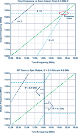
Figure 11. Static IF causes crossover spurs (top), using IF tuning to avoid crossover spurs (bottom)
Design Example - Broadband FDD System
To demonstrate the performance that this architecture can achieve, we built a receiver and transmitter FDD system prototype using ADI's finished devices. The operating frequency range of the receive band is configured from 12 GHz to 16 GHz, and the operating frequency range of the transmit frequency is 8 GHz to 12 GHz. Performance data was collected using an 5.1 GHz IF. The LO range of the receive channel is set to 17.1 GHz to 21.1 GHz, and the LO range of the transmit channel is set to 13.1 GHz to 17.1 GHz. The functional block diagram of the prototype is shown in Figure 12. In this figure, the X and Ku drive boards are shown on the left and the AD9371 evaluation board is shown on the right.
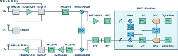
Figure 12. Functional block diagram of the X and Ku band Rx Tx FDD prototype system
Gain, noise figure and IIP3 data are collected on the receiving downconverter and shown in Figure 13 (top). Overall, the gain is approximately 20 dB, NF is approximately 6 dB, and IIP3 is approximately –2 dBm. Use the equalizer for additional gain adjustment or use the variable attenuator in the AD9371 to perform gain calibration.
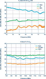
Figure 13. Ku-band Rx data (top), X-band Tx data (bottom)
The transmit upconverter was also measured and its gain, P1dB and OIP3 were recorded. The relationship between this data and frequency is shown in Figure 13 (below). The gain is approximately 27 dB, P1 dB is approximately 22 dBm, and OIP3 is approximately 32 dBm.
When this board is used with an integrated transceiver, the overall characteristics of reception and transmission are shown in Table 3.
Table 3. System overall performance table
| Rx, 12 GHz to 16 GHz | Tx, 8 GHz to 12 GHz | |||
| Gain | 36 dB | Output Power | 23 dBm | |
| Noise Figure | 6.8 dB | Noise floor | –132 dBc/Hz | |
| IIP3 | –3 dBm | OIP3 | 31 dBm | |
| Pin, maximum (no AGC) | –33 dBm | OP1dB | 22 dBm | |
| In-band m × n | –60 dBc | In-band spur | –70 dBc | |
| Power consumption | 3.4 W | Power consumption | 4.2 W |
Overall, receiver performance is comparable to superheterodyne architecture, while power consumption is greatly reduced. The receiver chain of equivalent superheterodyne design consumes more than 5 W. In addition, the construction of the prototype board was not prioritized by downsizing. Using the appropriate PCB layout techniques and integrating the AD9371 onto the same PCB as the downconverter, the total solution size for this architecture can be reduced to just 4 to 6 square inches, significantly less than nearly 8 to 10 square inches. Equivalent superheterodyne solution. In addition, technologies such as multi-chip modules (MCM) or systemized packages (SiP) can be further reduced in size. These advanced technologies can shrink the size to 2 to 3 square inches.
Conclusion
This article introduces a practical architecture - a high-IF architecture that replaces traditional methods and dramatically improves SWaP. The article briefly describes the superheterodyne architecture and important specifications for receiver design. It then introduces the high-IF architecture and explains its advantages in filtering requirements and integration (which reduces the total number of devices). We detail how to make a frequency plan and how to use the tunable IF to avoid interfering signals on the receiver. In terms of emissions, the goal is to reduce output spurs. We propose a way to avoid in-band spurs and predict all possible output spurious products.
The implementation of this architecture benefits from the rapid development of integrated direct conversion receivers in recent years. With the birth of the AD9371, higher performance can be achieved through advanced calibration and high integration. This architecture will become especially important in the future low SWaP market.
Wired Industrial Barcode Scanner
Wired Industrial Barcode Scanner,Industrial Barcode Reader,Industrial Handheld Barcode Scanner,Industrial Fixed Barcode Scanner
Guangzhou Winson Information Technology Co., Ltd. , https://www.barcodescanner-2d.com