In the design of single-chip system, the design of human-computer interaction interface of LCM (liquid crystal display module) is often a very important link. The LCM can be used for display setting parameters, status prompts, test results, and parameters to be entered on the smart instrument. In this paper, combined with the design requirements of the electrolyte analyzer, the liquid crystal display module YXD-12864A2LCM is used to study and realize the interface circuit and program design of the liquid crystal display based on the single chip C8051F020, and the button system is added to achieve the purpose of user convenience.
1 Introduction to Electrolyte Analyzer
The electrolyte analyzer (Electrolyte Analyzer) designed by this system is a high resolution and high precision instrument. It can be used with a variety of ion selective electrodes. It can be used to determine potassium, sodium, chloride and calcium ions in samples. Concentration and pH. Its structural block diagram is shown in Figure 1. The instrument adopts single chip C8051F020 as the core chip. In the measuring room, the potential signal of the electrolyte collected by the chemical sensor is sent to the signal conditioning circuit. After the signal is adjusted, it is sent to the main circuit board for A/D conversion, and then the output is displayed on the LCM, LCM. Parameters, display of measurement results, etc. can be operated by the keyboard. In communication with the host computer, data is transmitted using RS 232 communication. The instrument is characterized by being able to be used in a single machine or connected to a host computer. After connecting with the host computer, the interface operation can help the user to complete the functions of querying, storing, and real-time detecting the working status of the patient.
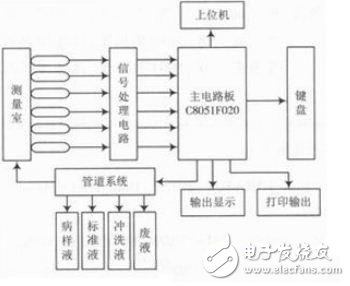
Figure 1 Block diagram of the electrolyte analyzer structure
The system display part adopts the graphic liquid crystal display module YXD-12864A2LCM, which is installed on the surface of the instrument to display the parameter setting, measurement result, calibration, quality control and so on. Interface display and parameter setting and page turning functions are realized by button control.
2 YXD-12864A2LCM
2.1 module introduction
YXD-12864A2LCM is a graphic dot matrix liquid crystal display module, which mainly consists of row driver, column driver and 128x64 full dot matrix liquid crystal display. The graphic display can be completed, and 4x8 (16&TImes; 16 dot matrix) Chinese characters can also be displayed. The YXD-12864A2 module has a total of 20 pins. Among them, the first pin VSS is connected to the system ground; the second pin VDD is connected to the power supply voltage; the third pin V0 is connected to the liquid crystal display driving power supply; the fourth pin D/I is connected to the data command selection signal; the fifth pin R/W is connected to the read/write selection. Signal; the 6th pin is connected to the read/write enable signal. When E is high, the data is read. When the falling edge of E comes, the data is latched to DB0~DB7; the 7th to 14th pins are connected to the tristate data bus. The 15th and 16th pins select the signal; the 17th pin is connected to the reset signal; the 18th pin Vout is connected to the internal negative voltage generator output voltage terminal; the 19th pin is connected to the LED backlight power supply positive terminal; the 20th pin is connected to the LED backlight power supply negative terminal.
2.2 interface circuit
The interface circuit diagram and schematic diagram are shown in Figure 2 and Figure 3. The P3 port of C8051F020 is connected as the data port to the DB port of the liquid crystal module; P2.0 is the reset pin control terminal; P2.1, P2.4, P2.5 are used as Ordinary I / O port use, respectively connected to the LCD module's enable terminal E, register select pin D / I, read and write pin R / W; P2.2, P2.3 respectively select the chip select signal left or right, Position the display.
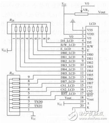
Figure 2 LCM interface circuit diagram
In the circuit diagram of Figure 2, R28 and R41 are pull-up resistors, because each port is connected to the microcontroller, the operating voltage is 5 V for the display, and the C8051F020 is 3.3 V, which makes the C8051F020 output better. To drive a 5 V input LCM, each port is connected to a 5 V supply through a pull-up resistor. This ensures that the logic "1" output of the C8051F020 can be boosted to 5 V.
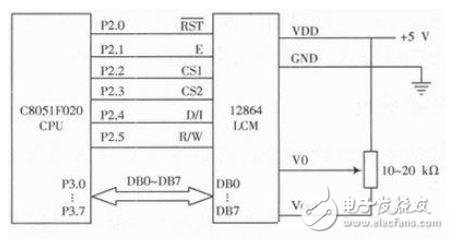
Figure 3 interface circuit schematic
2.3 software design
Display character: Displays the specified string starting from the position specified on the screen. The LCM is a 128x64-bit liquid crystal display, and the dot matrix occupied by each character is 8x8. The display position is determined by two coordinate parameter data, and the abscissa x represents "row", and the value ranges from 0 to 7; Corresponding to the top line of the screen, the 7th line corresponds to the bottom line. The ordinate y represents "column", the value ranges from 0 to 15, the 0th column corresponds to the leftmost column of the screen, and the 15th column corresponds to the rightmost column of the screen.
Suppose you want to display the character "K" from the position in column 4 of row 4, the program segment is as follows:
;entrancd: C(left,right), R4(X), R5(Y), DPTR, R6(length)
Data_to_lcd:
SETB CS1_LCD
CLR CS2_LCD
JNC data_to_lcd2
CLR CS1_LCD
SETB CS2_LCD
Data_to_lcd2:
MOV A, R4
LCALL display_X_line
MOV A, R5
LCALL display_Y_line
MOV A, R6
MOV R7, A
LCALL write_LCD_bytes
MOV A, R4
INC A
LCALL display_X_line
MOV A, R5
LCALL display_Y_line
MOV A, R6
MOV R7, A
INC DPTR
LCALL write_LCD_bytes
CLR CS2_LCD
CLR CS1_LCD
RET
SETB C; chip select settings
MOV R4, #04H; location line number
MOV R5, #08H; position column number
MOV DPTR, #K; character content
MOV R6, #08; defines the length of the character
LCALL data_to_lcd; a subroutine that calls the output character
08*16 2835 Led Neon Flex,Neon Flexible,Neon Flex Light,Neon Flex Led Strip
NINGBO SENTU ART AND CRAFT CO.,LTD. , https://www.lightworld-sentu.com