1. Introduction
Currently, in China, the hollow sucker rod induction heating system utilizes a power frequency induction heating method. To balance three-phase power, the power frequency heating power supply superimposes one phase of the three-phase AC through a reactor and capacitor to the other two phases. Then, it is transformed into suitable heating conditions for various applications by a transformer, connecting the heating conductor with single-phase power frequency AC. However, this traditional method is costly, bulky, inefficient, and difficult to manage.
The oil medium frequency induction heating power supply uses IGBT as the inverter switching device, reducing the size by 40% and the weight by 50% compared to conventional power frequency sources. This makes it more efficient and easier to integrate into modern systems.
2. Medium Frequency Induction Heating Power Supply
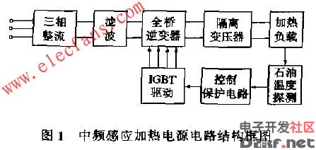
Figure 1 shows the circuit structure of the medium frequency induction heating power supply. The three-phase rectifier converts the power frequency three-phase AC into DC. After filtering, the full-bridge inverter converts it into a single-phase intermediate frequency AC with adjustable frequency and duty cycle. It then outputs to the isolation transformer, which heats the load. The full-bridge inverter uses a PWM zero-voltage switching circuit, offering low switching losses and minimal electromagnetic interference [2]. The control circuit employs the SG3524 IC block to regulate the 9-pin voltage, ensuring a proper dead time for the output signal. The pulse width is modulated based on the temperature detected by a petroleum sensor, maintaining the oil temperature between 45°C and 70°C. Too high or too low a temperature can affect the chemical properties and fluidity of the oil.
3. IGBT Gate Drive Circuit
3.1 Selection of IGBT Gate Drive Module
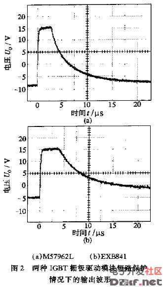
IGBT gate drive modules such as EXB841 and M57962L are suitable for driving IGBT modules within the 1200V series up to 400A, featuring overcurrent detection and protection. Under short-circuit conditions, their output waveforms are shown in Figure 2. The EXB841 internally generates a 5V negative bias that cannot be adjusted, while the M57962L uses an external Zener diode to produce a 9V negative bias, offering better gate reliability. Additionally, the M57962L has a faster protection response time (6.3μs) compared to the EXB841 (16μs), making it more reliable and safer for use.
3.2 Improvement of Peripheral Circuit of Drive Module
When the IGBT turns off, the voltage rise rate between the collector and emitter can reach up to 30,000V/μs. This high rate can cause significant displacement current and lead to large collector pulse surges, increasing the risk of dynamic failure in the IGBT. To prevent this, a negative bias must be applied to the IGBT’s gate. However, in practical applications, two situations may cause the loss of this negative bias: 1) the Zener diode breaks down due to a short circuit; 2) the drive circuit loses its +24V power supply.
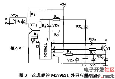
To address these issues, the author improved the peripheral circuit of the M57962L IGBT driver module, as shown in Figure 3. Under normal operation, VZ4 is activated, keeping the 8th pin of M57962L high and VD1 off. If the Zener diode VZ1 or VZ3 shorts, VZ4 turns off, VT1 is disabled, and VO1 goes into a high-impedance state. Similarly, if the drive circuit loses +24V, VO1 also enters a high-impedance state, ensuring safe operation.
4. IGBT Module and Filter Capacitor Connection
The input characteristics of the IGBT are similar to those of a MOSFET, with high input impedance. If the drive circuit loses power, the IGBT's gate will lose its negative bias, leading to potential interference and simultaneous conduction of the upper and lower IGBTs. If the IGBT is directly connected to a filter capacitor with several thousand microfarads, the stored energy could be released through the upper and lower tubes, potentially damaging the IGBT module. Therefore, the induction heating power supply first activates the control and drive circuits before connecting the IGBT and filter capacitor. When turning off, the IGBT is disconnected from the capacitor first, followed by deactivating the control and drive circuits.
5. Test Results and Conclusion
The oil-assisted induction heating power supply has been operating normally since the field test at the second test plant in June 1997. With a power output of 3588kW, this system is not only applicable to the hollow sucker rod induction heating system but also to the medium frequency induction electric heating system used in complex small fault block oilfields. Its implementation significantly reduces capital investment and operational costs, making it a valuable solution for pipeline heating systems.
Smart Multimeter ,Smart Digital Multimeter,Digital Smart Multimeter,Multimeter Smart
YINTE TOOLS (NINGBO) CO., LTD , https://www.yinte-tools.com