When a metal resistance strain gauge is used in mechanical measurements, it must be combined with a bridge circuit. Since the output signal from the strain gauge bridge is weak, using a DC amplifier can lead to zero drift. To avoid this issue, an AC amplifier is typically used for signal amplification. As a result, the strain gauge bridge is usually powered by alternating current, forming an AC bridge.
Depending on the reading method, bridges are generally divided into two types: balanced and unbalanced. Balanced bridges are mainly used for measuring static parameters, while unbalanced bridges are more suitable for dynamic measurements.
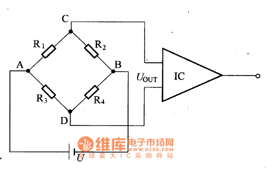
The circuit shown represents a DC unbalanced bridge connected to an amplifier. The first bridge arm is connected to the resistance strain gauge R1, while the other three arms use fixed resistors. When no strain occurs, the bridge remains in balance, so the output voltage is zero:
UOUT = A(R1·R4 - R2·R3) = 0
However, when the strain gauge is subjected to strain, its resistance changes by ΔR1, causing the bridge to become unbalanced.
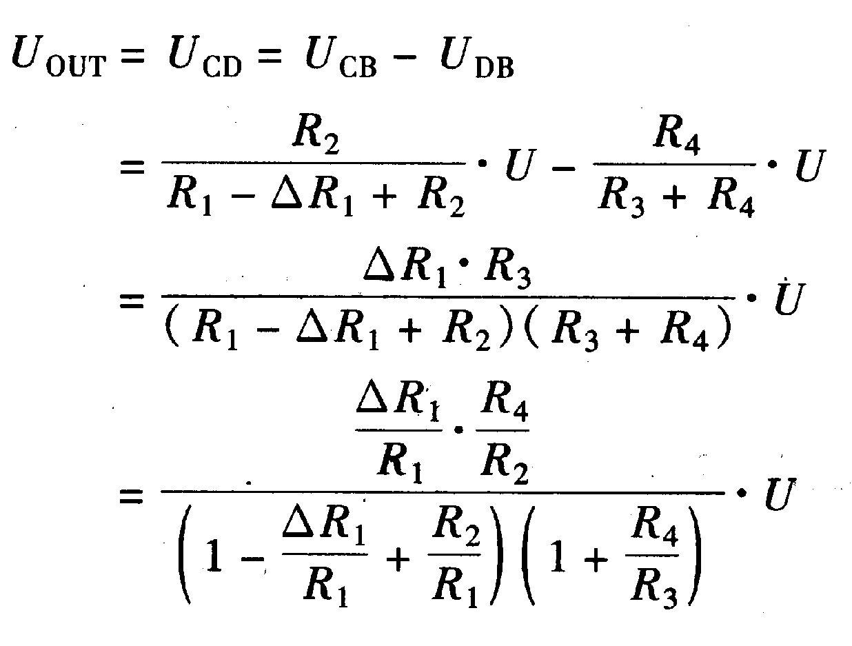
Assuming 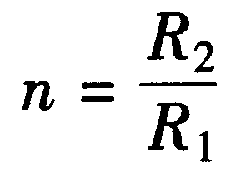 and considering the initial balance condition of the bridge
 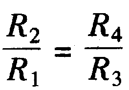 , we can ignore the small terms in the denominator
 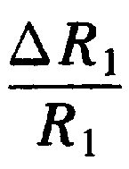 , resulting in the following simplified expression:

From this equation, it's clear that the output voltage is directly proportional to the change in resistance caused by the strain on the gauge. This relationship is crucial for accurately measuring mechanical deformation in various engineering applications.

A solar cell panel, solar electric panel, photo-voltaic (PV) module, PV panel or solar panel is an assembly of photovoltaic solar cells mounted in a (usually rectangular) frame, and a neatly organised collection of PV panels is called a photovoltaic system or solar array. Solar panels capture sunlight as a source of radiant energy, which is converted into electric energy in the form of direct current (DC) electricity. Arrays of a photovoltaic system can be used to generate solar electricity that supplies electrical equipment directly, or feeds power back into an alternate current (AC) grid via an inverter system.
Solar Panel,200w Folding Solar Panel,Folding Solar Portable Power Station,Sunpower Solar Cell
suzhou whaylan new energy technology co., ltd , https://www.xinlingvideo.com