Charger (Charger) is a device that provides energy for power storage devices. It is widely used in mobile phones, cameras, MP3, MP4 and other common digital products. The products on the market are all distributed chargers, which are charged by the mains, but some are not available in the mains or the power sockets are not compatible, remote areas, travel, especially when there is no power supply, it is not convenient to charge, the multi-source is designed. The digital charger can be charged under any conditions: without mains, it can be charged with 2 1.5 V dry batteries. With no dry battery, it can be charged with 3.7 V internal battery. Even without any charging equipment, you can use hand pressure to generate electricity. Machine to charge digital products. The above is the special feature of this charger, and it is also special in this design: charging digital products anytime, anywhere.
1 Design requirements refer to relevant national standards, mobile communication handset chargers should meet the following requirements:
1) Input voltage AC charger input limit AC voltage range should be 100 ~ 240 V, tolerance is ± 10%.
2) The output voltage of the output voltage charger should be 5 V DC and the tolerance is ±5%.
3) The output current range of the output current charger should be 300~1 800 mA.
4) Output ripple 1 output current ripple: When the input voltage (90 ~ 264 V), the voltage range on the analog load (1.50 ~ 4.75 V), the output ripple limit is less than or equal to 100 mA peak. 2 Output voltage ripple: When the input voltage (90 ~ 264 V), the voltage range on the analog load (1.50 ~ 4.75 V), the output ripple limit is less than or equal to 200 mV peak. 3 Short-circuit current: When the input voltage (90 ~ 264V), the load is short-circuited, and the short-circuit current limit is less than 950 mA.
5) Current reflow In any case, the current measured by the handheld to the charger should be no more than 5 mA regardless of whether the charger is plugged in or not.
6) When the input voltage (100~240 V) is no load energy consumption, the load is open and the output ripple limit is less than 300 mW.
7) Average efficiency of the charger The average efficiency of the charger should be no less than 50%.
8) Dry battery charging design requires charging current not higher than 200 mA.
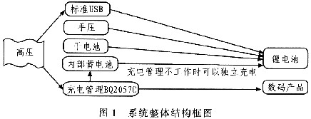
2 system overall design charger is divided into high voltage, charge management, boost, logic control lighting, internal battery, dry battery, manual pressing and other functional modules. The overall structure of the system is shown in Figure 1.
This article refers to the address: http://
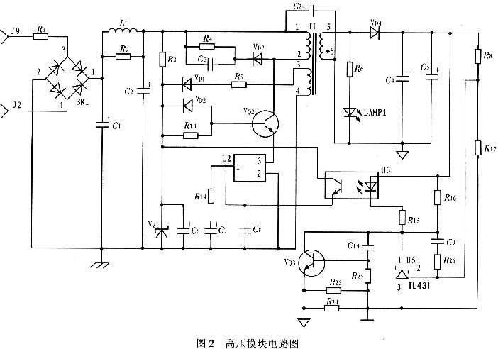
2.1 High-voltage module This circuit is connected to the AC 220 V rectifier bridge to form a DC voltage. After C1 and C2 filtering, the voltage is applied to the C-pole of the triode VQ2 via the 1, 2 pins of the switching transformer T1. The voltage provides a forward bias voltage to the base (B) of transistor VQ2, turning transistor VQ2 on. R4, the infinite capacitor C4 and the Schottky diode VD3 provide protection. At this time, the oscillating circuit starts to work. The current in the l and 2 pins of the switching transformer T1 passes. The induced voltage at the 3 and 4 pins of the transformer T1 is applied to the base of the transistor VQ2 through the resistor R12, so that the base current of the VQ2 is turned on. Increase and quickly enter the saturation zone. When the current is greater than 0.5 A, U2 is turned on, the base voltage of VQ2 is pulled low, the collector (C) current begins to decrease, and the magnetic flux generated by the pins 1 and 2 of the transformer T1 also begins to decrease. The VQ3 part is a current limiting function. When R23 and R24 increase, the current decreases, and when it decreases, the current increases. TL431 is a constant current source, and the output voltage is stable at 5 V, so that the optocoupler works, so that the oscillating voltage is continuously generated in the circuit, and a 5 V DC voltage is induced at the 6-pin of the transformer T1, and the capacitor is rectified by the diode VD4. After C4, C5 filtering, external digital products are charged through standard USB. Figure 2 is a circuit diagram of the high voltage module.
2.2 Charge Management Device BQ2057
In this charger, the internal battery is charged after the mains is turned on, and the output voltage of the device is 4.2 V, so that the external digital product is charged through the SMT socket. During the charging process, the current begins to flow at a constant current and gradually decreases, while the voltage gradually rises to a final constant voltage. Charging is complete when the current approaches zero.
2.3 Logic Control Light Module When the dry battery is connected, press the switch light to illuminate, then press the light to turn off. The light in this module is a flashlight for illumination with a current of no more than 200 mA.
3 PCB design The usual chargers are single-panel, and the volume is relatively small, and the developed charger is a double-panel. Considering the shape and size of the charger casing, there are more components and patches; because there is a hand pressing device. , so pay attention to the placement of components.
4 Data measurement According to the requirements of national standards, in the experiment: 1) When the input voltage range is between 90 and 264 V, the output DC voltage at no load is 4.77~4.96 V, and the output current is at O. 31~0.32 A; 2) When testing current ripple, the noise is very small. When the input voltage is 90~260 V, the voltage on the analog load is 1.49~4.75 V, and the output current ripple limit is 150 mA/5. 6 Ω ~ 160 mA / 11 Ω; 3) When testing voltage ripple, the input voltage is 90 ~ 260 V, the voltage on the analog load is 1.49 ~ 4.75 V, the output voltage ripple limit is 150 ~ 160 mV; 4) When the input voltage is short-circuited from 9 to 260 V, the short-circuit current limit is 540 to 800 mA: 5) When the input voltage is 100 to 260 V, the power consumption limit is 2.9 mA × 100 V to 1 mAx 240 V; When the input voltage is 220 V, the input power is 640 mW when the input current is 12 mA. The output voltage is 5.1 V, the output power is 1 530 mW when the output current is 0.3 A: 7) The average efficiency is 57%; 8) The current is not backflow during the measurement. The test results show that the charger is fully compliant with national standards.
The high-voltage module and the charging management module are used to charge the external digital product, and the test data of the voltage and current during charging and the trend of the change are given.
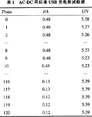
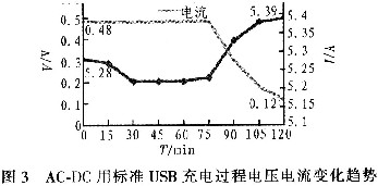
1) Use the standard USB to charge the external digital products through the mains. The battery is 910mAh, and the voltage and current changes are recorded every l min. The data of this experiment is shown in Table 1. The change trend of voltage and current during charging process is shown in Fig. 3. It is obvious from Fig. 3 that the voltage of the charging process gradually rises from the beginning of 5.28 V and the final constant voltage is 539 V. The current gradually decreases from the beginning of 480 mA constant flow. Charging completed in 121 minutes.
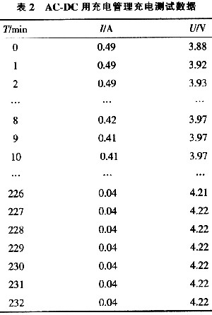
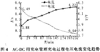
2) Use the mains to charge the external digital products through the charge management. The battery is 910 mAh, and the voltage and current changes are recorded every 1 min. The data of this experiment is shown in Table 2. The trend of voltage and current during charging process is shown in Figure 4. From Figure 4, the voltage and current trend can be seen. The voltage of the charging process gradually rises from the beginning of 3.88V and the final constant voltage is 4.22 V. The current gradually flows from the beginning of 490 mA. decline. It is completed by charging in 232 minutes.
3) The charger uses the mains to charge the lithium battery through the standard USB. The charging process results are shown in Table 1 and Figure 3; the utility battery is used to charge the internal battery through the charging management device, and the digital product is charged through the SMT socket. The process results are shown in Table 2 and Figure 4. In the case where there is no mains or in the remote place, it is inconvenient to use the mains charging. The lithium battery can be charged by the internal battery, and the lithium battery can be charged by the external dry battery. The lithium battery can be charged for about 20 minutes with a dry battery; another unique device is a hand-press generator, which is designed to be used even in the absence of any other device that can be used to charge digital products. It is also possible to use a hand-pressed generator to manually generate electricity, to charge external digital products anytime and anywhere, and to provide an illumination lamp, which is used as an emergency light in the event of a power outage or no lighting.
5 Conclusion This charger is different from all other similar products in that it can use a variety of resources to charge digital products under any circumstances. It can also charge products with battery and charge management. In addition, there are lightings. No charger is available. After testing, the charger has high repeatability, indicating that the design of this charger is feasible.
High Frequency PCB
High frequency PCB also called HF PCB.The RF frequency range is typically from 500 MHz to 2 GHz, and designs above 100 MHz are considered RF. The microwave frequency range is anything above 2 GHz. There`s a considerable difference between RF and microwave circuits versus typical digital and analog circuits. In essence, RF signals are very high frequency analog signals. Therefore, unlike digital, at any point in time an RF signal can be at any voltage and current level between minimum and maximum limits. We have much experience in this filed,up to 60 GHz PCB we made.
1.Made of special Resin system material with Low ER and Low loss factor
2.Hybrid Build up mix of FR4 with Low loss material3.Tight Impedance control
4.Used in Automotive, Radar, CAR to CAR communication, Distance Assistance, Active Drive Systems
We say high frequency ,also like RF PCB and Microwave PCB as they are special material too,not usual FR4 .We have Taconic,Rogers,F4B,F4BM.PTFE material in stock.With this,we can do your special boards quick turn.Unlike other suppliers need long time to purchase material.
RF PCB
RF PCB,RF Electronic PCB,RF Design PCB,Specialize Flex RF PCB
Storm Circuit Technology Ltd , http://www.stormpcb.com