The typical characteristics of the electro-hydraulic position servo control system are non-linearity, uncertainty, time-varying, external interference and cross-coupling interference, etc. The system's accurate mathematical model is not easy to establish. Therefore, the control of the electro-hydraulic system has always been a complex control system problem.
The conventional PID controller has the characteristics of simple structure, clear parameter meaning, excellent dynamic and static characteristics of the control and so on. Artificial neural network (NNC) has the ability of information synthesis, learning memory and self-adaptation, and the ability to approximate any nonlinear function. It can handle processes that are difficult to describe with models and rules, but there are also local minimum points, which are not easy to achieve optimal control.
Combining NNC and PID control to form an intelligent controller can achieve better control effects. Here we propose to use DSP to implement NNC-PID controller to intelligently control the electro-hydraulic position system to meet the fast and high response of the electro-hydraulic position servo to the control system. Precision requirements.
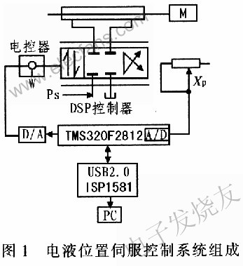
1 Composition of electro-hydraulic position servo system
Taking the first joint of the painting manipulator as an object, a research experimental device was constructed, as shown in Figure 1. The feedback device uses a precision conductive plastic potentiometer. The entire control system takes DSP as the core and consists of the first joint of the painting robot, position sensor, 12-bit A / D converter and D / A converter, signal conditioning circuit and output amplification drive circuit, and the host computer PC. Servo tracking control.
2 Control system hardware design
TMS320F2812 is the 2000 series of digital signal processing (DSP) launched by TI, mainly used in the field of control. With a frequency of 150 MHz, a fixed-point 32-bit CPU can run 16 × 16 and 32 × 32 operations. On-chip up to 128 KB of program memory, 128 KB of ROM and 18 KB of SARAM, external interface 16-bit data line and 19-bit address line, can be expanded 1 MB of ROM. In addition, a 16-channel 12-bit A / D converter is integrated, with a minimum cycle time of 80 ns, and 56 individually programmable general-purpose I / 0 (GPIO) pins. High-speed digital signal processing capabilities and abundant external expansion resources make the TMS320F2812 suitable for applications in demanding control systems.
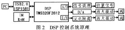
2.1 Overall structure of the control system
The control system adopts the control scheme of PC + DSP, and the overall structure of the system is shown in Figure 2. The PC is mainly used to display the control interface, adjust various control parameters, and display various related signals in real time. The DSP completes the low-level control function, collects various signals through the A / D converter, and after certain algorithm processing, it is output by the D / A port, and the electromagnetic circuit is driven by the I / 0 port and photoelectric isolation to control the electromagnetic Valve switch. At the same time, through communication, the collected signals are sent to the PC, and the PC start and stop commands and control parameters are received.
2.2 A / D conversion circuit
The clock of A / D converter module of TMS320F2812 can reach 25 MHz, the conversion precision is 12 bits, and it can collect 16 channels of 0 ~ 3 V voltage analog signals. Multiple trigger modes: software trigger (DOC), event manager A (EVA), event manager B (EVB). The relationship between the conversion data and the input voltage is: digital value = 4 095x (V input-VADCLO) / 3, where VADCLO is the reference voltage of each channel.
When wiring the PCB, the distance from the signal introduction end to the TMS320F2812 pin should be as short as possible, and at the same time, each channel should be far away from the digital signal and be spread on a large area. In the A / D converter circuit module, J3 is connected to the sensor, J19 can be connected to the oscilloscope, etc., which can be used by other instruments to collect data.
2.3 I / O and drive design
The I / 0 board is mainly used to drive each solenoid valve. The drive current can reach several amperes. The electromagnetic noise is large. The switch of each relay will generate strong electromagnetic interference. The current impact of the switch and the peak voltage are large, which will affect the DSP. run. Therefore, the wiring board is separated from the DSP main board. In the I / O board design, 74LS244 is used as the driving element, and TLP521 is used as the photoelectric isolation and relay to drive the external load. In PCB wiring, the wire through which a large current passes is appropriately thickened, and the board can drive 8-way (expandable to 16-way) solenoid valves.
2.4 Communication circuit
ISPl581 used in the design of the USB communication circuit is a universal serial bus interface device of Philips, which fully complies with the USB2.0 specification. Support USB2.0 self-check working mode and USBl.1 return working mode, directly connected with ATA / ATAPI peripherals, integrated 8 Kbyte multi-structure FIF0 memory; high-speed DMA interface: 7 0UT endpoints and a fixed Control IN / OUT endpoint. Through a high-speed universal parallel interface, ISPl581 provides high-speed USB communication capabilities for microcontroller / microprocessor-based systems. Using the existing structure and referenced firmware not only shortens development time, but also reduces development risks and costs. It is a simple and economical USB peripheral solution.
Map ISPl581 to XINTF ZoneO space of TMS320F2812, use
2.5 External expansion memory circuit
TMS320F2812 maps the external storage space into five 16-bit zones, XINTF Zone0 to XINTF Zone2, XINTF Zone 6, and XINTF Zone7. Among them XINTF ZoneO and XINTF Z0nel are 8 KB, and share chip select signal
3 Neural network NNC-PID controller
Neural network is a highly nonlinear ultra-large-scale continuous-time dynamic system, with large-scale parallel distributed processing, a high degree of robustness, adaptability and learning association capabilities. It can adapt itself to changes in the environment and modify itself. Process parameters, these characteristics provide great potential for the application of neural networks to the control of electro-hydraulic position servo systems.
3.1 Neural network PID control system structure
The structure of the neural network PID control system is shown in Figure 3 (a). It can be seen from the control system block diagram that the neural network PID control includes two control sub-modules: NNI is the controlled object model recognizer, and NNC is the neural network PID controller. The working principle of the NNC-PID control system is: first obtain the input and output sample pairs of the actual controlled object, and then use the NNI to perform offline recognition of the controlled object. When the recognition accuracy reaches the set requirements, adjust the weight of the NNC in real time The coefficient makes the coefficient adaptive, so as to achieve the purpose of effective control.
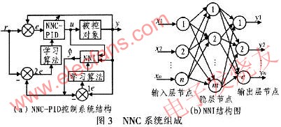
3.2 Neural network identifier (controlled object model identifier NNI)
The neural network identifier NNI is implemented with a 3-layer serial-parallel BP network, including an input layer, a hidden layer, and an output layer. Its structure is shown in Figure 3 (b). The input of the network is the input / output sequence of the controlled object [u (k), y (k)], and the output of the network is the teacher signal
The input and output of the hidden layer of the network are:
3.3 Neural network NNC-PID controller (single neuron adaptive NNC-PID controller)
Because the controlled object model is uncertain, uncertain, and there is random disturbance from the outside world, in order to achieve higher control accuracy, a single neuron adaptive NNC-PID controller structure is used on the basis of the offline identification of the controlled object model ,As shown in Figure 4.
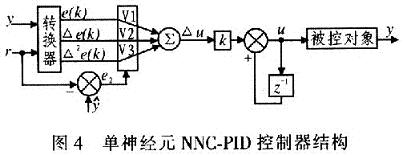
The weight coefficient value of the network V = [v1, v2, v3], that is, the three coefficients KP, KI, KD that characterize the PID controller. , The input of the network is X = [x1, x2, x3], that is, characterize the three input parameters e (k), â–³ e (k), â–³ 2e (k), and the output of the network is â–³ u (k).
The supervised Hebb learning rule realizes the self-adaptive and self-organizing function by adjusting the weight coefficients. The control algorithm and learning algorithm are shown in formula (10) and formula (11).
According to the supervised Hebb learning rule, the weight coefficients are adjusted as follows according to the formula (12) to (14):
In the formula, K is the neuron proportional coefficient, and ηI, ηP, and ηD are the learning rates of integral, proportional, and derivative, respectively.
4 System software design
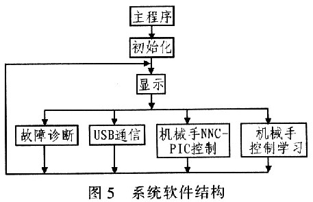
The software design of the system is mainly divided into two parts, a PC program written in Labview and a DSP program written in C language, in which the PC program is used to display and process the data sent by the DSP, and send instructions and adjustment parameters to the DSP .
DSP system software design is designed and written in C language under the development system of CCS2000, using top-down design ideas, and dividing the software modules according to functions. The system software is shown in Figure 5, mainly by the initialization module, fault diagnosis, It consists of USB communication module, manipulator NNC control learning module and manipulator NNC-PID control module.
5 Test results
For the electro-hydraulic position servo manipulator system, the conventional PID control is first used, and the Ziegler-Nichols method is used to tune the PID parameters, that is, the control system adjusts the proportional gain under pure proportional control, so that the system reaches critical stability, and the gain ku and The critical oscillation period Tu can determine the PID parameters, namely: kp = 0.6Tu, kI = 0.5Tu, kD = 0.25Tu, and finally determine the proportional, integral, and differential coefficients: kP = 1.02, kI = 0.024, kD = 0.006, then the positional step response of the coefficient is shown in Figure 6. Under the same circumstances, the neural network NNC-PID control method is used to control the electro-hydraulic position servo manipulator system, and the initial weight of NNC is the PID setting value, that is: v1 (0) = 1.02, V2 (0) = 0.024, V3 (0) = 0.00 6, in order to ensure the stability of the iteration, limit the iteration range of the weight: 0.1≤v (1) ≤1.3, 0.001≤v (2) ≤0.06, 0.001≤v (3) ≤5 At this time, the system's position tracking response curve is shown in Figure 6. It can be seen from the comparison that using the neural network NNC-PID method, due to its learning ability, the system quickly converges to the position steady state value. The neural network NNC-PID control can improve the control performance of the system because it can adjust the PID parameters in real time. At the same time, it shows good robustness to the time-varying parameters, which solves the nonlinear and time-varying parameters of the hydraulic system.

It should be noted that the choice of neuron proportional coefficient K has the most important impact on the control performance of the system. Too large or too small will cause the system performance to deteriorate, and even self-optimization and adaptation cannot be achieved. The impact of ηP, ηI, ηD on the performance of the system is reflected in the speed of the learning speed.
6 Conclusion
By analyzing the characteristics of electro-hydraulic position servo manipulator operation and debugging and its requirements for the controller circuit, a PC + DSP control scheme based on neural network NNC-PID controller is adopted to control the electro-hydraulic position servo PC + DSP The system is designed with hardware and software, and the functions, characteristics and plate making requirements of each control subsystem of the hardware are analyzed in detail. The software design process of the controller based on neural network NNC-PID and the compilation and debugging of the software are explained. After laboratory comparison and operation instructions, the electro-hydraulic position servo manipulator PC + DSP control system based on the neural network NNC-PID controller has a good control effect, the controller works reliably, and the parameter adjustment is convenient.
Guangzhou Ehang Electronic Co., Ltd. , https://www.ehangmobile.com