There are 5 types of errors in the CAN bus :
Bit error: A node sending a bit to the bus is also monitoring the bus. When the level of the monitored bus bit is different from the sent level, 9 detects a bit error at that bit. However, when the recessive bit is sent during the filling bit stream of the arbitration area or the acknowledgement gap sends a dominant bit, it is not considered to be an error bit. A transmitter that sends an acknowledgement error label is not considered an error bit when it detects a dominant bit.
Stuffing error: In the message encoded with the bit stuffing method, when the sixth consecutive bit level occurs, a stuffing error will be detected.
CRC error: The CRC sequence is composed of the result of the CRC calculation of the transmitter. The receiver calculates the CRC in the same way as the transmitter. If the calculation result is different from the received CRC sequence, a CRC error is detected.
Form error: When one or more illegal bits appear in the fixed-form bit area, a form error is detected.
Response error: During the response gap, when the transmitter does not detect a dominant bit, it detects a response error.
Nodes that have detected an error condition are calibrated by sending an error flag. When any node detects a bit error, stuffing error, form error, or response error, the node starts sending the error flag at the next bit.
In the CAN bus, any unit may be in one of the following three fault states: error activation state (ErrorAcTIve), error approval state (Error PasiTIve) and bus off state (Bus off).
The error activation unit can participate in the bus communication as usual, and when an error is detected, an active error flag is sent. Error recognition nodes can participate in bus communication, but are not allowed to send active error flags. When it detects an error, it can only send an acknowledge error flag, and it is still in the error acknowledge state after transmission until the next transmission is initialized. The bus off state does not allow the unit to have any influence on the bus.
In order to define the fault, there are 2 counts in each bus unit: send error count and receive error count. These counts are performed according to the following rules.
(1) When the receiver detects an error, the receiver error counter is incremented by 1, unless all detected errors are bit errors during the transmission of active error flags or overload flags.
(2) When the receiver checks the dominant bit after sending the error flag, the error counter increases by 8.
(3) When the transmitter sends an error flag, the transmitter error counter is increased by 8. There are two exceptions: one is that if the transmitter is falsely acknowledged, the dominant bit is not detected or the response error is detected, and when the acknowledge error flag is sent, the dominant bit is not detected; If the arbitration device generates a fill error, the transmitter sends a recessive bit error flag, and the dominant bit is detected. Except for the above two cases, the transmitter error counter does not change.
(4) When the transmitter sends an active error flag or overload flag, a bit error is detected, and the transmitter error counter is increased by 8.
(5) After sending the active praseodymium error flag, the approval error flag, or the overload error flag, any node can allow up to 7 consecutive dominant bits. After detecting the 11th consecutive dominant bit, or immediately following the recognition error flag, the 8th consecutive dominant bit, and the additional 8 consecutive dominant bits for each sequence, each transmitter ’s The transmission error count is increased by 8, and the reception error count of each receiver is also increased by 8.
(6) After the message is successfully sent, the send error count is decremented by 1, unless the count value is already 0.
(7) After the message is successfully sent, if the receive error count is between 1 and 197, its value is reduced by 1; if the receive error count is 0, it remains at 0; if it is greater than 127, its value is recorded as 119 A value between ~ 127.
(8) When the sending error count is equal to or greater than 128, or the receiving error count is equal to or greater than 128, the node enters into the wrong recognition, and the status is sent, the node sends an active error flag.
(9) When the sending error counter is greater than or equal to 256, the node enters the bus off state.
(1O) When both the sending error count and the receiving error count are less than or equal to 127, the error recognition node becomes the error activation node again.
(11) After detecting that 11 consecutive recessive bits on the bus are sent 128 times, the bus off node will become two error activation nodes with both error counters being 0.
(12) When the value of the error counter is greater than 96, it means that the bus is seriously interfered.
If only one node hangs on the bus during system startup, after this node sends out a message, it will not get a response, check the error and repeat the message, at this time the node can become an error recognition node, but it will not Therefore, the bus is turned off.
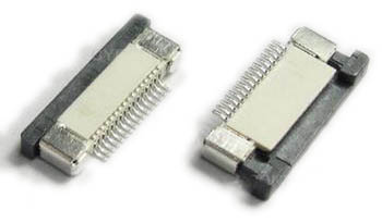
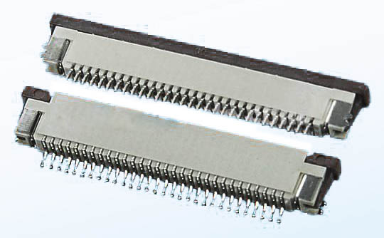
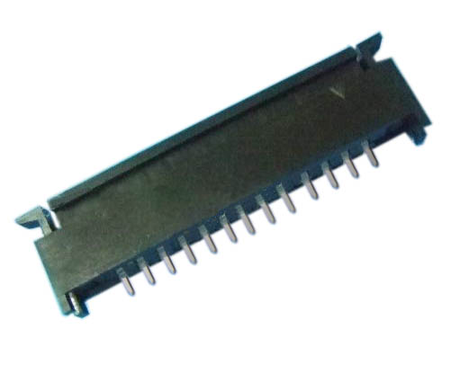
1.ANTENK Flexible Printed Circuit (FPC) and Flexible Flat Cable (FFC) connectors are ZIF (zero insertion force) and LIF (low insertion force) connectors designed to provide a fast, easy, reliable method to make a connection of flexible printed circuits to a PCB. Adam Tech`s special contact design completely preserves conductor integrity by eliminating all wiping action while making connection. Flex circuitry enters the connector and the connector cap is pressed down to capture the flex circuit producing a stable, high pressure connection. Raising the cap releases the pressure for exchange or replacement of circuitry. This series includes single and dual row versions in thru-hole or SMT mounting in vertical or horizontal orientations.
2.Our products are widely used in electronic equipments,such as monitors ,electronic instruments,computer motherboards,program-controlled switchboards,LED,digital cameras,MP4 players,a variety of removable storage disks,cordless telephones,walkie-talkies,mobile phones,digital home appliances and electronic toys,high-speed train,aviation,communication station,Military and so on


FFC Connector Range Available as:
0.3,0.5, 0.8, 1.0,1.25, 2.54mm connector pitch
Surface mount
Side and Top entry
Side entry parts - Top and bottom contact options
ZIF (Zero Insertion Force)
Slide and flip lock actuator styles
Specifications:
Material And Finish:
Insulator: LCP
Lock: PPS
Insert Spring:Phosphor Bronze,
Matte Tin Plated
Solder Platten Area:Phosphor
Bronze,Matte Tin Plated
Voltage:500 V AC(rms)/DC
Current:0.5 A AC(rms)/DC
Contact Resistance:20 mΩ max(initial)
Insulation Resistance:800 MΩ min
Operating Temp:-20°-85°
Fpc Connector,Fpc Cable Connectors,Ffc Cable Connectors,Pitch Fpc Connector,Surface mount FPC/FFC Connectors,Top entry FFC Connectors, Side entry FFC Connectors
ShenZhen Antenk Electronics Co,Ltd , https://www.antenk.com