Headphone amplifier requirements
--- The headphone amplifier is mainly used in portable audio devices. Like other portable electronic products, it requires devices with low operating voltage, low power consumption, and small size packaging. The headphone amplifier also has its own technical parameter requirements, which require small total harmonic distortion plus noise (THD + N), high power supply rejection rate (PSSR), high signal-to-noise ratio (SNR), and high efficiency. Different amplifiers also have different additional functions, such as built-in digital volume control and built-in DAC. Specific performance indicators are as follows.
â— Output power POUT
--- The output power of the headphone amplifier is small, generally 20 ~ 100mW (the actual output power is related to the size of the operating voltage, and is related to the size of the load resistance and the size of THD + N). The load resistance of a stereo headset is generally 16Ω or 32Ω, and the output power with a small load resistance is larger.
â— THD + N
--- THD + N index is generally in the range of 0.01% to 0.2%, Hi-Fi level is less than 0.01%. This index is related to the size of the load resistance RL and the output power POUT. If the RL is different and the POUT is different, the index is quite different. For example, for the same headphone amplifier, when RL = 32Ω, POUT = 12mW, f = 1kHz, THD + N = 0.006%; and when RL = 16Ω, POUT = 15mW, f = 1kHz, THD + N = 0.015%. Therefore, when comparing the THD + N specifications of different headphone amplifiers, they must be comparable when the basic conditions are similar.
â— SNR
--- SNR is generally in the range of 60 ~ 90dB, its size is related to POUT, and some products can achieve SNR of about 100dB.
â— PSRR
--- Headphone amplifier with high PSRR, its performance is less affected by the power supply voltage changes (amplifiers with high PSRR can be powered without a regulated power supply). PSRR is generally 60 ~ 80dB, good performance up to 90dB. Welcome to reprint, this article comes from the electronic enthusiast network (http: //)
Lower operating voltage
--- In order to reduce the volume and weight of portable products, the most effective method is to use lithium ion batteries with high energy density and small volume, but lithium ion batteries are expensive. Using 1 to 2 alkaline batteries or rechargeable batteries to supply power, the manufacturing and use costs will be much reduced. In recent years, some manufacturers have developed headphone amplifiers powered by only one battery (one 5 # or 7 # alkaline battery or nickel-metal hydride, nickel-cadmium battery), which is more popular with consumers, and its operating voltage is 0.9V ~ 1.8V It can be powered by either one alkaline battery or one rechargeable battery, which has greatly reduced the cost of some low-end MP3 players and increased sales.
--- Because it is powered by a single power supply, the voltage amplitude of the headphone amplifier output is affected by the operating voltage. Although an amplifier with rail-to-rail output can be used, the output of a 1V operating voltage is always less than 1V.
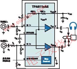
--- In order to reduce the operating voltage, it is also necessary to ensure a sufficiently large output voltage amplitude, a voltage-reversed charge pump circuit is integrated in the headphone amplifier to convert the input VDD to -VDD, then the headphone amplifier is powered by a single power supply Turned into a positive and negative power supply, the output voltage amplitude doubled, as shown in Figure 1.
Measures to reduce peripheral components
--- The typical application circuit of Texas Instruments TPA611xA2 headphone amplifier is shown in Figure 2. The two 325kΩ resistors inside the amplifier form a voltage divider, which provides the bias voltage (1 / 2VDD) of the two channel op amps, and has a SHUTDOWN terminal (active low level) to turn off the amplifier and consume power Less than 10μA.
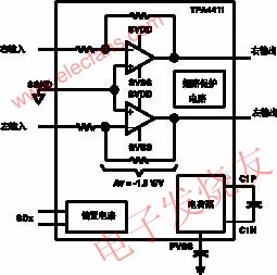
--- Reducing peripheral components not only saves printed circuit board area, but also improves performance. Figure 3 shows the internal structure and peripheral components of the headphone amplifier TPA4411 launched by Texas Instruments in August 2004. TPA4411 uses fixed gain (AV = -1.5V / V), no output DC blocking capacitor is needed, simplifying peripheral components, and has the following advantages: reducing PCB area; reducing component cost; improving THD + N performance; no need to consider output capacitor Effect on low frequency response. Compared with Fig. 3, Fig. 2 has reduced 4 gain setting resistors and saved two output capacitors.
--- In order to solve the amplifier gain requirements of different audio devices, Maxim Corporation (MAXIM) launched the headphone amplifier MAX9725 in November 2004. There are different gains for users to choose. / V, -1.5V / V, -1V / V and -4V / V. It can also be seen from Figure 1 that the new headphone amplifier reduces external components.

Add additional functions
--- Headphone amplifiers with good performance generally have shutdown control, overheat protection and short circuit protection, suppress startup / shutdown noise (click and pop noise), and noise suppression function. The new headphone amplifier also adds other additional functions, such as digital volume control (with I2C interface and digital volume circuit), built-in DAC, left and right channel line output, etc.

--- MAX9850 is a headphone amplifier with DAC launched by Meixin Company in November 2004 and has a stereo line output. The device uses a single power supply 1.8 ~ 3.6V power supply; when 1.8V power supply can output 30mW; no output capacitor; PSRR at 1kHz is 91dB; clock frequency can reach 40MHz; flexible I2S compatible digital audio interface; I2C headset volume and static Noise control; stereo line input and output; no click and pop sound; two-wire (I2C) compatible control interface; 28-pin QFN package. The device is mainly used in MP3 players, portable multimedia players, mobile phones, smart phones, portable DVDs, etc.
--- The typical application circuit of MAX9850 is shown as in Fig. 4. In Figure 4, stereo headphones can be plugged into HPL, HPS, HPR headphone jacks. In addition, the output from the OUTL and OUTR lines enters the MAX9701 power amplifier through a 0.47μF input capacitor to drive the left and right speakers.
--- NJW1109 launched by JRC Japan is a headphone amplifier with electronic volume control. Figure 5 is a block diagram of the internal structure of the device. The microprocessor controls the volume through SDA and SCL. The device has a built-in 1 / 2V + bias circuit (Bias) with an external 10μF bypass capacitor at the Vref terminal. INa and INb are audio signal inputs, and OUTa and OUTb are two outputs (connected to stereo headphones). SDA is the I2C bus data input, SCL is the I2C bus clock input, and ADR is the I2C bus slave address selection terminal. The device is available in 14-pin DIP, DMP and SSOP packages.

Adopt Class D high efficiency amplifier
--- Class D switching audio amplifiers have high efficiency, and are generally used in power amplifiers with output power of several watts or tens of watts. In order to extend battery life and reduce power consumption, this type of amplifier is also used in new mobile phones, PDAs, and portable audio devices. For example, National Semiconductor ’s LM4666, launched in May 2004, is a high-efficiency stereo 1.2W switching audio amplifier. When the operating voltage is 3V, the load resistance RL = 8Ω, and the output power POUT = 100mW, the typical efficiency can reach 79 %. The typical application circuit is shown in Figure 6. Welcome to reprint, this article comes from the electronic enthusiast network (http: //)
--- The characteristics of the device include: no output filter is required; a gain of 6dB or 12dB can be selected; few external components; there are "click" and "pop sound" suppression circuits; there is micro-power shutdown control; there is short circuit protection; small 14-pin SDA package. Gain selection (GAIN SELECT) when the high level is terminated, the gain is 6dB, when it is low level, it is 12dB. SHUTDOWN closes when it is connected to low level.
3D printing on the pen machine is mainly used in 3 d printing pen, is made from a special custom Dc Gear Motor, mainly used in 3 d printing pen, pen 3 d printing machine has been updated three generations according to the requirements of product.
3D Printing Motor product introduction:
The 3D Printing Motor is based on the deceleration Motor, coupled with supporting gears and ball bearings.The role of the gear reducer is to provide lower speed and greater torque.At the same time, gear box different deceleration ratio can provide different speed and torque.It's mostly rolling.


Features: 3D Printing Motor, small size, large torque, low noise, durable, low energy consumption, customized power design, convenient installation and maintenance;
Simplify design and save space.
Features: usually used financial equipment, office equipment, electronic locks, wireless charger, remote control toys, precision instruments and meters, automobile industry, medical equipment, consumer electronics, household appliances, electric glass doors and Windows, etc., wide application range
Method of use: the best stable in horizontal plane, installed on the 3D Printing Motor output shaft parts, cannot use a hammer to knock, knock prone to press into the 3D Printing Motor drive, may cause damage to internal components, and cannot be used in the case of blocked.


Operating temperature range:
3D Printing Motor should be used at a temperature of -10~60℃.
The figures stated in the catalog specifications are based on use at ordinary room temperature catalog specifications re based on use at ordinary room temperature (approximately20~25℃.
If a 3D Printing Motor is used outside the prescribed temperature range,the grease on the gearhead area will become unable to function normally and the motor will become unable to start.Depending on the temperature conditions ,it may be possible to deal with them by changing the grease of the motor's parts.Please feel free to consult with us about this.
Storage temperature range:
3D Printing Motor should be stored ta a temperature of -15~65℃.
In case of storage outside this range,the grease on the gearhead area will become unable to function normally and the motor will become unable to start.
Service life:
The longevity of 3D Printing Motor is greatly affected by the load conditions , the mode of operation,the environment of use ,etc.Therefore,it is necessary to check the conditions under which the product will actually be used .The following conditions will have a negative effect on longevity.Please consult with us should any of them apply.â—Use with a load that exceeds the rated torque
â—Frequent starting
â—Momentary reversals of turning direction
â—Impact loads
â—Long-term continuous operation
â—Forced turning using the output shaft
â—Use in which the permitted overhang load or the permitted thrust load is exceeded
â—A pulse drive ,e.g.,a short break,counter electromotive force,PWM control
â—Use of a voltage that is nonstandard as regards the rated voltage
â—Use outside the prescribed temperature or relative-humidity range,or in a special environment.
â—Please consult with us about these or any other conditions of use that may apply,so that we can be sure that you select the most appropriate model.
when it come to volume production,we're a major player as well .each month,we rurn out 600000 units,all of which are compliant with the rohs directive.Have any questions or special needed, please contact us, we have the engineer group and best sales department to service to you Looking forward to your inquiry. Welcome to our factory.

3D Printing Motor
3D Printing Motor,3D Printing Gear Motor,3D Printing Pen Motor,3D Printing Spindle Motor
Shenzhen Shunchang Motor Co., LTD. , https://www.scgearmotor.com