At present, radio and television are in the transition and development stage from analog technology to digital technology, one-way broadcasting to two-way interactive transmission, and basic services to expansion and value-added services. Digital cable TV set-top boxes are the product of this stage of development. With set-top boxes, people can not only watch digital TV programs with the original analog TV, but also use the digital set-top box interactive functions to obtain value-added electronic program guides (EPG), video on demand (VOD), e-mail, data broadcasting, and distance education service. For specific operations, it is necessary to install a set-top box on the analog TV set of the user terminal to complete the access of digital TV signals and data, and complete the decoding and output of video and audio signals. This article introduces the hardware design of the set-top box system.
Device selection
When choosing a chip, in addition to satisfying the basic functions of receiving digital TV, users must also be able to achieve high-speed Internet access through the cable TV network. That is, they must have two basic application modules, STB and Cable Modem. According to this demand, the design selected the interactive digital TV set-top box single chip CX24430 of CONEXANT (Conexant) company as the core to design the entire system.
The overall structure of the system
This system takes CX24430 chip as the core, and also includes a cable tuner (Tuner), upstream power amplifier, flash memory used for curing programs and storing program parameters, SDRAM, EEPROM, audio DAC and audio and video output used in conjunction with CPU processing and data storage. Circuit and power supply unit, etc. In addition, there are MulTI-ICE interface for software debugging and RS23 interface for terminal monitoring, as well as USB interface, 1394 interface and Ethernet physical layer RJ45 interface. System block diagram shown in Figure 1.
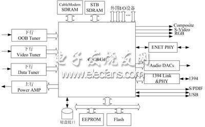
Figure 1 Block diagram of the set-top box terminal system
The main innovation of this system design is that the system uses a dual-CPU architecture, and independently supports the operation of the Cable Modem and the system's application programs. The basic work flow is: After the digital TV signal is transmitted from the TV station to the user through the cable, it needs to go through multiple processes to restore the original image and sound. First, demodulate and decode the channel, and then decode the output transport stream, including demultiplexing, audio and video decoding, graphics processing, video encoding, and audio DAC.
Hardware design of main modules
1 Design of the front-end access part of the system
The front-end RF access signal of the integrated service digital cable TV dual-mode set-top box mainly includes the data stream in the downstream band (including audio and video and IP networks), the data stream in the downstream band and the upstream data stream (including in-band and out-of-band); The in-band frequency channel is used to transmit audio and video and IP network data, and the out-band frequency channel is mainly used to transmit the control parameters and interactive information of the cable modem terminal system (CMTS) at the head end of the CATV network and the user's set-top box. Moreover, various information and data are processed in parallel through frequency division multiplexing and time division multiplexing on the HFC network.
The design of the front-end access part is shown in Figure 2. Among them, PMX1338C is an integrated module that receives radio frequency signals, including LNA low-noise amplifiers, diplexers (isolating the transmitted and received RF signals) and signal splitters (distributing downstream signals to the corresponding ports); MT1530 contains Mixing filter and upstream signal power amplification; CX2443x is used for digital decoding and encoding and output to external interface.
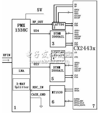
Figure 2 System front-end access circuit diagram
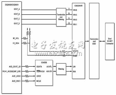
Figure 3 Set-top box receiving system back-end circuit diagram
Circuit design of audio and video output
In the set-top box receiving system, the video and audio decoder of the CX2443x back-end subsystem constitute the system audio and video output interface; the decoded audio and video signals are sent from the semiconductor crystal to the stereo DAC CS4335, or from the dual audio / video signal switch CX2161R. The circuit of the audio and video signal output part is shown in Figure 3.
Outdoor decorative LED mesh curtain screen is the perfect architectural decoration patterns in the daytime and night. And it becomes Led Display Screen to display image and video at night;Outdoor decorative Led Curtain Screen is ultra light weight design, which is easy to install. The convenient installation help everyone can install it easily by oneself. It can be packaged in one CMB which is save a lot in transportation. It is not only good for transport but also good for maintenance. Front and back maintain are available due to its special design;LED curtain mesh screen can be installed directly on the wall or glass. The hollow design makes permeability up to 70% which is conducive to ventilation and lighting. The exquisite appearance is good for decoration of shopping mall, hotel, office building and 5s shop etc;The frame shell save install material can be fixed easily. High-intensity sealed lamp with high quality up to IP67 protection level.
It is not only good for transport but also good for maintenance. Front and back maintain are available due to its special design.LED curtain mesh screen can be installed directly on the wall or glass. The hollow design makes permeability up to 70% which is conducive to ventilation and lighting. The exquisite appearance is good for decoration of shopping mall, hotel, office building and 5s shop etc.
Curtain Led Display,Transparent Curtain Led Display,Rgb Curtain Led Display,Soft Led Curtain Display Screen
Shenzhen Bako Vision Technology Co., Ltd. , http://www.rentalleddisplays.com