For many applications and ECUs in the automotive environment, the voltage provided by the battery and the generator will be insufficient, and it must first be converted to the correct voltage level. Generally, DC / DC switching voltage regulators and linear regulators are used to achieve this goal. This article will focus on the discussion of switching regulators because the linear scheme cannot produce an output voltage higher than the input voltage.
The most commonly used topology is a buck converter (Figure 1). Only a single inductor and a set of diodes and switches are needed to achieve one of the simplest and most cost-effective options in a switched DC / DC solution. However, the only drawback is that this method can only produce an output voltage that is lower than the input voltage. If the output voltage needs to be higher than the input voltage, a "reverse" topology or boost converter can be used (Figure 2). The components required for this topology are similar, but can produce an output voltage that is higher than the input voltage.
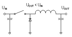
Figure 1: Basic buck converter
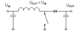
Figure 2: Basic boost converter
Since the fluctuation of the automotive grid voltage is quite large (it can be as low as 3.5V at startup and can be as high as 45V during the clamp load dump), so in some ECU applications, the input and output voltages must cross Situation. During the start-up process (starting the engine), sudden disability is not allowed, especially for power system applications or certain navigation and infotainment systems. This problem can be solved by using a flyback converter or SEPIC topology, but the transformer type The extra cost and space of the inductor is relatively large, making it less attractive to customers.
Even if the input voltage crosses the output voltage value, the buck-boost topology can still provide a stable output voltage, and it has a simple design using only a single coil. In the same topology, it combines a buck and a boost converter. The seamless transition between the two different modes can produce a stable and uninterrupted output voltage under all input voltage conditions.
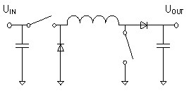
Figure 3: Asynchronous buck-boost converter
Two different topologies are combined here, so compared to a simple buck or boost method using a set of switches and diodes, an asynchronous buck-boost converter requires two sets of switches and diodes (Figure 3). In order to improve the overall efficiency, the diode can be replaced with a switch. The current topology and inductance look similar to a complete H-bridge (Figure 4).
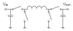
Figure 4 Switch replaces diode
The general functions of these devices can be subdivided into three modes of operation:
1. Buck mode when input voltage is higher than output voltage
2. Boost mode with input voltage lower than output voltage
3. The transfer of input voltage in the output voltage range
Buck mode operation
In operation in buck mode, the input voltage must be higher than the output voltage, similar in function to the basic buck topology. In the buck mode, the converter's boost switches (B1 and B2) will not switch, and the B1 switch must be off, which allows current to flow from the inductor to the output capacitor. The B2 switch must be turned on to avoid short-circuiting the output to ground (GND).
When switching to "on time", the A1 switch is turned off to charge the inductor (Figure 5). During this period, current flows from the input through the A1 switch, coil, and B1 switch, and into the output capacitor.
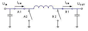
Figure 5: Current flow of the buck converter during the conduction phase
In the second phase of the cycle (off time), the A1 switch will turn on and the A2 switch will turn off (Figure 6). The magnetizing coil will force the current from GND to flow through the A2 switch, coil, B1 switch, and then into the output capacitor (also known as the flywheel).
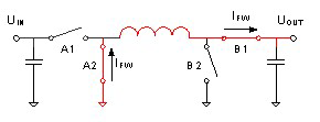
Figure 6: Current flow of the buck converter in the flywheel stage
In the asynchronous topology, the A2 switch is replaced by a diode as a passive flywheel component. This reduces the number of drivers and field-effect transistors (FETs) used, but it also reduces the efficiency of the converter. The switching duty cycle in this operation is based on the input-to-output voltage ratio shown in Equation 1.
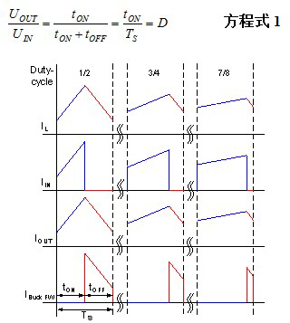
Figure 7: Current waveform during buck switching
Face Shield,Safety Face Shield,Medical Face Shield,Protective Face Shield
Ningbo Anbo United Electric Appliance Co.,ltd , https://www.airfryerfactory.com