Foreword
This article refers to the address: http://
In recent years, power steering systems have become the standard for some cars, and about half of the world's cars use power steering. With the development of automotive electronics technology, some cars have used electric power steering (EPS), which has improved the economy, power and mobility of the car. The EPS uses the power generated by the electric motor to assist the driver in power steering. It is generally composed of a torque (steering) sensor, an electronic control unit, an electric motor, a speed reducer, a mechanical steering gear, and a battery power source. When the car is turning, the torque (steering) sensor will "feel" the torque to the steering wheel and the direction of rotation. These signals will be sent to the electronic control unit through the data bus. The electronic control unit will according to the driving torque, the direction of the intended rotation, etc. The data signal sends an action command to the motor controller, so that the motor outputs a corresponding amount of rotational torque according to the specific needs, thereby generating a power steering. If you do not turn, the system will not work and is in a dormant state. Due to the working characteristics of electric power steering, drivers will feel better in direction and more stable at high speeds. Moreover, since it does not work when it is not turned, and only requires no hydraulic power, the conventional power steering system can save energy by about 80% under various driving conditions, thereby improving the running performance of the vehicle. It has been rapidly promoted in recent years and is also the development direction of the power steering system in the future.
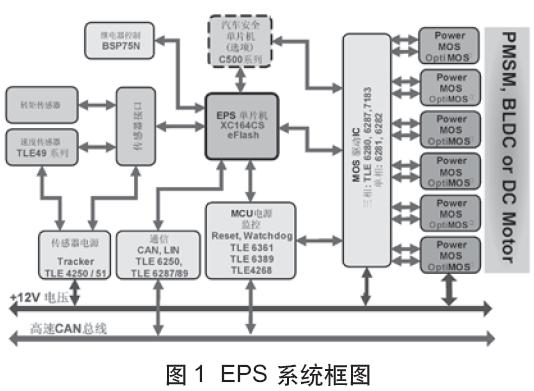
Figure 1 shows a typical electric power steering system, the core of which is a motor variable frequency speed control system. Because the permanent magnet synchronous motor (PMSM) has the characteristics of simple structure, small size, light weight, low loss, high efficiency, etc., compared with the DC motor, it has no mechanical commutator and brush, and it does not need to be compared with the asynchronous motor. Reactive excitation current, thus high power factor, small volume, small current and stator resistance loss, and rotor parameters can be measured, fixed rotor air gap, good control performance, is the first choice for automotive electric power steering system.
The vector control of permanent magnet synchronous motor generally controls the stator current or voltage by detecting or estimating the position and amplitude of the rotor flux of the motor. Thus, the torque of the motor is only related to the flux and current, similar to the control method of the DC motor. , can get very high control performance. For the permanent magnet synchronous motor, the rotor flux position is the same as the rotor mechanical position, so that the magnetic flux position of the motor rotor can be known by detecting the actual position of the rotor, so that the vector control of the permanent magnet synchronous motor is compared with the vector control of the asynchronous motor. Simplified. In applications where high precision, high dynamic performance and small size are required, the application of PMSM motor servo systems has significant advantages. This article is devoted to the design of a PMSM motor servo system for EPS systems. The system uses XC164CM as the core control chip of the EPS system, and uses the stator field orientation principle (FOC) to realize the servo control of the permanent magnet synchronous motor. The experimental results show that the system is reasonable in design, reliable in performance and very targeted.
XC164CM and CAPCOM6E
The XC164CM is a new derivative of the widely used C166 series of microcontrollers. It is based on the enhanced C166S V2 architecture and is superior to the existing 16-bit solution. The XC164CM's powerful DSP performance and advanced interrupt handling, combined with a variety of efficient and flexible peripherals and high-performance on-chip Flash make it an ideal choice for industrial and automotive applications. Its flexible intelligent PWM unit CAPCOM6E provides PWM control for various motors such as AC motor (AC), DC brushless motor (BLDC) and switched reluctance motor (SRM). High-speed, high-resolution and synchronous triggering ADCs can quickly and accurately convert complex analog environment variables. The high-speed TwinCAN module with automatic gateway function enables an efficient networked solution. The XC164CM is packaged as P-TQFP-100, and the block diagram is shown in Figure 2.

The C166S V2 has many advantages over the C166. First, it uses an enhanced Harvard architecture (program memory and data memory have their own multi-bandwidth bus), a single-cycle instruction set, and 40 MIPS instruction execution speed at 40 MHz CPU clock. Secondly, it not only has a 5-level instruction pipeline, but also adds a 2-stage prefetch instruction pipeline, which has unparalleled program branch prediction and judgment ability, thus achieving zero-cycle program jump. In addition to high-speed hardware multiply/divide units, it also integrates a single-cycle multiplier (MAC) unit to provide powerful DSP functions (including the DSP instruction set), which greatly enhances its computing power. The matching DSP function library enables users to quickly and easily implement various DSP operations such as FIR, IIR, FFT, and so on. The C166S V2 also integrates an on-chip debug system (OCDS) with a JTAG interface.
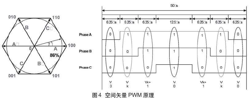
The intelligent PWM unit CAPCOM6E of the XC164CM is shown in Figure 3. It can generate various types of PWM waveforms, such as SPWM, Space Vector PWM (SVPWM) and so on. This system uses SVPWM, and its generation principle is shown in Figure 4. The eight possible switching states form six possible magnetic field directions (plus two zero vectors), and the magnetic field vector can reach all points in the hexagon (the operating region of the inverter) and cannot exceed the hexagon. The PWM switching frequency is 20KHz.
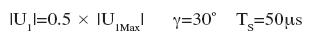
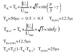
Its time calculation formula (30o) is:
Field Oriented (FOC) Control and Its Implementation
To establish a mathematical model of the rotor shaft (d, q-axis) of a permanent magnet synchronous motor, the following assumptions are made:
· Ignore the saturation of the motor core;
· Excluding the eddy current and hysteresis loss of the motor;
• The rotor has no damper windings.
Under the above assumption, the motor voltage equation expressed by the rotor reference coordinate (axis) is as follows:
Stator voltage equation

Where: ud, uq is d, q-axis voltage; id, iq is d, q-axis current; Ld, Lq is the equivalent inductance of stator inductance under d, q-axis; Rs is stator resistance; we is rotor electrical angular velocity Yf is the flux linkage of the rotor excitation field through the stator winding; p is the differential operator; Pn is the motor pole pair; wm is the rotor mechanical speed; J is the moment of inertia; TL is the load torque.
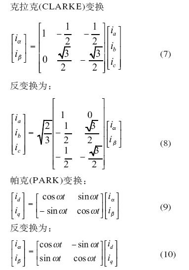
The above equation is obtained by transforming the a, b, c coordinate system to the d, q rotor coordinate system. Here, the rotor shaft is taken as the d-axis, and the q-axis is advanced by 90o in the direction of rotation. Its coordinate transformation is as follows:
Clark (CLARKE) transformation
From the perspective of rotor coordinates, the stator current can be divided into two parts, namely the torque current iq and the excitation current id. Therefore, id = 0 is usually used in vector control to ensure maximum output torque with minimum current amplitude. At this time, the motor torque expression of equation (5) is 
It can be seen from equation (11) that both Pn and yf are internal parameters of the motor, and their values ​​are constant. To obtain a constant torque output, as long as the control iq is constant. From the analysis of the d and q axes above, the direction of iq can be determined by detecting the rotor axis. Thereby, the vector control of the permanent magnet synchronous motor is greatly simplified. The field oriented control (FOC) of the entire PMSM motor is shown in Figure 5. 
The hardware of PMSM motor control system with XC164CM as the core is shown in Figure 6. The control circuit of the whole system consists of XC164CM. As the control core, XC164CM judges the working mode of the system after receiving external information, and converts it into the switching signal output of the inverter. After the driving circuit, the signal directly drives the power MOSFET to supply power to the motor.

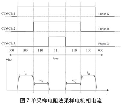
Current sampling circuit
Usually vector control of PMSM motors requires sampling of two-phase motor stator currents such as ia and ic. However, the system samples the DC bus current through a single sampling resistor, and combines the actual output PWM combination to infer the actual motor stator phase current. The XC164CM's ADC can be set to be triggered synchronously by the rising/falling edge of the PWM waveform. Obviously, this method can sample two phase currents twice in one PWM switching cycle, as shown in Figure 7.
Rotor position detection circuit
The rotor position feedback of the motor adopts an incremental photoelectric encoder with a resolution of 2000 pulses/rev, wherein the A and B signals are 90° out of phase (electrical angle), and the XC164CM can obtain the phase and number of A and B. Motor steering and speed. The position of the motor rotor and the rotational speed of the motor are determined by collecting these signals.
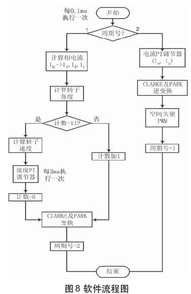
software design
The system software consists of two parts: the main program and various functional modules such as current sampling, speed and position calculation, speed PI control, current PI control, CLARKE and PARK transform and inverse transform, space vector PWM and so on. The main program completes the initialization of the system, the I/O interface control signals, the settings of the various control module registers in the XC164CM, and then enters the infinite loop program. Each function module is executed at regular intervals based on the PWM period. The entire software flow is shown in Figure 8.
The time taken to actually measure each major functional module is shown in Table 1.
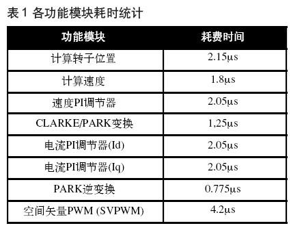
The simulation and experimental results show that the system has fast dynamic response and high control precision, which can fully meet the requirements of electric power steering system. It is particularly worth noting that the powerful DSP function of the XC164CM can complete a series of complex calculations in a short period of time, which not only ensures the real-time performance of the PMSM motor vector control, but also ensures the smooth implementation of other tasks of the EPS system.
Conclusion
In this paper, the technical key of electric power steering system - the field oriented control system of PMSM motor is discussed in detail. The system uses XC164CM as the controller on the hardware. The circuit design is simple and compact, which meets the system requirements. At the same time, the fully digital control makes the system greatly improved in control accuracy, function and anti-interference ability. The powerful DSP function of the XC164CM, the intelligent PWM generating unit and the high-performance ADC make the system realize high-performance EPS system with only a few additional circuit components, which has a good market application prospect. In addition, the reasonable design of the system software structure also ensures the real-time and stability of the system.
Rubber keypad Membrane Switches = Rubber Keypad + Membrane Switch
> Why need Rubber Keypad Switches?
As we know the common membrane switch is usually use PET and PC film as the graphic overlay. The product can be very thin, usually less than 1mm.
But sometimes many customers design their product to be rubber keypad switches. Because of that rubber can give users a very good touch feeling.
In addition, rubber keypads can make carbon pills on the backside of the buttons, the carbon pills are conductive, then it can be combined with PCB circuit
very easily. We only need make the gold plated conductive pads on the PCB, then assemble the rubber keypad with PCB, when you press the buttons, the
carbon pills will connected to the gold pads, then trigger function.
The rubber keypad switches also can achieve the backlighting easily. As we know the rubber raw material usually is translucent. It is light through. After painted we wanted colors on the rubber, we only need laser etch the backlit symbols and letters, then the LED light from the backside of PCB or membrane circuit can be through the etched area out to get the backlit effect.
Rubber is easy to clean, so once the keypad is contaminated you can clean it very easily. Rubber keypad's press life also is very high. At least 1,000,000 times above. It is very durable and not easy damaged. So the rubber keypad switches are widely used in machinery, industrial manufacturing, vending machine, dirty and oil contamination environment and others.
Rubber Keypad Switches
Rubber Keypad Switches,Backlight Rubber Keypad,Silicone Rubber Keyboard Switches,Tactile Rubber Membrane Switch
Dongguan LuPhi Electronics Technology Co., Ltd. , http://www.luphiprint.com