1 Introduction
This article refers to the address: http://
With the continuous development of automotive electronic technology and network technology, people have higher and higher requirements for vehicle safety and reliability. In order to solve the communication problem caused by the increase of automotive electronic components, this requires a kind of High-speed, multi-channel, shared car communication network.
At present, various buses have been developed, such as CAN (Controller Area Network) controller LAN [1], LIN (Local Interconnect Network) local area network [2], FlexRay, Most, and the like. But CAN and LIN constitute the most extensive form of bus on the car today.
2 CAN bus introduction
In the late 1980s, Bosch developed a serial communication protocol CAN[1] to solve the real-time data exchange between many control units and test instruments in modern automobiles, and made it an international standard (ISO11898). So far, the world has more than 20 CAN bus controller chip manufacturers, more than 110 CAN bus protocol controller chips and microcontroller chips integrated with CAN bus protocol controller.
Thanks to its unique design and new technology, the CAN bus offers outstanding reliability, real-time and flexibility compared to the general communication bus. CAN adopts multi-master working mode, low cost and high bus utilization; CAN bus has reliable error handling and error detection mechanism, adopts short frame structure, short transmission time, low probability of interference; non-destructive Bus arbitration technology, the node has an automatic exit function in case of serious error.
3 LIN bus introduction
In 1998, Audi, Motorola, BMW, DaimlerChrysler, VCT, Volvo and Volkswagen jointly proposed a new Class A bus [3-5] - LIN (Local Interconnect Network). LIN is a low-cost, short-range, low-speed network that is designed to transmit changes in state such as switch settings and sensor inputs, and is responsive to such changes, so it is only suitable for low-speed events that do not require high transmission times. Not suitable for high speed events such as engine control.
The LIN bus has its unique features, its low cost, based on the universal UART/SCI interface; LIN's transfer rate can be as high as 20Kb/s, the bus length can reach up to 40m; single-master multi-slave mode, no bus arbitration is required; Self-synchronization can be achieved from the node without the crystal oscillator and ceramic oscillator clock: the propagation time of the deterministic signal can be pre-calculated; nodes can be added or deleted on the network without changing the hardware and software of the LIN slave node.
3 vehicle system communication network design
The communication system of the whole vehicle system is mainly based on CAN bus, supplemented by LIN bus. CAN and LIN are combined in the vehicle communication network to jointly construct the communication system of the vehicle system. Each control system on the vehicle is sensitive to the transmission delay of network information. For example, engine control, transmission control, airbag control, ASR/ABS/ESP control, traction control, etc. have high requirements for real-time transmission of network information, and high speed is required. CAN bus, its transmission rate is up to 500kbps ~ 1Mbps; air conditioning control, instrument control, wiper control, lighting control, door and window control, etc. need to use low-speed LIN bus, its transmission rate is 20kbps. The low-speed LIN bus does not require real-time information transmission, but the number of subsystems is large. Separating these low-speed subsystems from high-speed subsystems helps to ensure the real-time performance of high-speed subsystems while reducing costs. Based on the above considerations, the topology diagram of the CAN/LIN bus network of the vehicle is shown in Figure 1.
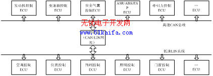
The CAN and LIN buses are independent of each other and share data and exchange data through the main controller (CAN/LIN gateway). The main controller is also the core of the vehicle management system. Its main function is to analyze and process various information and issue instructions, and also to coordinate the work of various control units and electrical equipment of the vehicle.
4 system hardware and software design
4.1 CAN / LIN interface design
There are many CAN nodes and LIN nodes in the CAN/LIN network, which implement data communication between CAN/LIN networks through a CAN/LIN interface gateway. The CAN/LIN bus interface design is shown in Figure 2. Through the CAN/LIN bus interface, CAN and LIN data can be converted to each other through the central controller. When the LIN data frame needs to be transmitted to the CAN network, the controller gateway receives the LIN bus. After the data frame, the LIN identifier is converted to the CAN identifier, so that the data is transferred from the LIN bus to the CAN bus, and vice versa. The data can also be transferred from the CAN bus to the LIN bus.
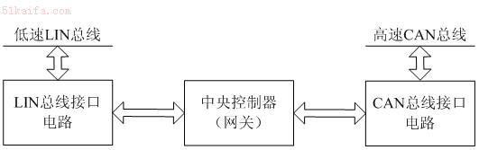
Figure 2 Automotive CAN/LIN bus network topology
4.2 CAN communication network hardware design
Figure 3 is a schematic diagram of the CAN bus communication interface card circuit. The system uses the P87C591 chip as the main controller. The electronic control unit's microcontroller (P87C591) is directly connected to the CAN bus controller (SJA1000) via a data bus via an opto-isolator (6N137). The CAN bus controller has a receive buffer and a transmit buffer. The CAN bus controller's transmit port Tx0, the receive ports Rx0 and Rx1 are directly connected to the CAN bus transceiver's TxD, RxD, and Vref ports, respectively. The two differential receive transmit lines CAN_L and CAN_H are each connected to a 120 bus match resistor. When the CAN bus is occupied by a node, the transmitting end of the node is connected to CAN_H, the level is 3.5V, the receiving end is connected to CAN_L, and the level is 1.5V. When the CAN bus is idle, the levels on CAN_H and CAN_L are all 2.5V.
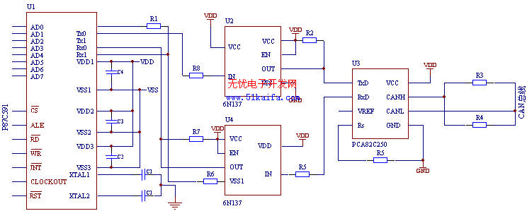
Figure 3 CAN bus node circuit schematic
The system uses the PCA82C250 as the interface between the CAN controller P87C591 and the physical layer bus to provide data transmission and reception to the bus. Using the PCA82C250 can also improve the system's anti-interference ability, protect the bus, reduce radio frequency interference, and achieve thermal protection.
In order to further improve the anti-interference ability of the system, the high-speed optoelectronic isolation chip 6N137 is used to form an isolation circuit, and the I/O signal of the microcontroller P87C591 is isolated from the SJA1000 to improve the reliability of the system.
4.3 LIN communication network hardware design

Figure 4 LIN bus node circuit schematic
Figure 4 is a schematic diagram of the LIN bus node circuit. The hardware interface circuit of the LIN node mainly includes the microcontroller P87LPC76X, the LIN transceiver MC33399 and the power supply adjustment circuit. The P87LPC76X uses the 80C51 to accelerate the processor architecture, and the instruction execution speed is twice that of the standard 80C51MCU. The microcontroller sends data from TX0 to the TXD of the MC33399, and the RXD of the MC33399 sends data to the RX0 of the microcontroller. The circuit uses the Wake pin input switch wake-up mode, where the 5V external regulator is controllable. Since the circuit internally integrates a resistor and a series diode on the LIN pin and the power supply pin, the bus slave node does not require other external components. But for the master node, the resistor must be added externally, and a diode must be connected in series to prevent the MC33399 from being powered by the bus when the battery is powered off.
4.3 CAN/LIN bus software design
The CAN communication interface module program mainly includes three parts: an initialization subroutine, a transmission subroutine (including an interrupt service program), and a receiving subroutine. At the beginning of the program, the program is initialized. There are three ways to enter the initialization program: one is hardware reset; the other is software reset; the third is power-on reset. The initialization program initializes all message objects (all values ​​are set to 0). After the initialization is completed, the program starts to read the switch state and enters the CAN transmission subroutine. In the CAN transmission subroutine, the data can be transmitted only when the transmission buffer is empty, otherwise it will wait until the transmission buffer is empty. The receiving subroutine reads the received data from the receiving buffer and can receive it after being processed by the program.
The LIN communication interface module program also mainly includes three parts: a LIN initialization subroutine, a transmission subroutine (including an interrupt service program), and a receiving subroutine. During the initialization phase, the LIN transceiver is configured and the protocol handles the initial values ​​of its variables. As with the CAN master node software subroutine, data can only be sent when the transmit buffer is empty. The central controller node is the master node of the LIN bus, the others are slave nodes, all LIN frames are sent by the master node, and the master node is responsible for the monitoring and management of the LIN node.
4 Conclusion
At present, CAN bus has been applied as a reliable automotive computer network bus in many automobiles, and many scholars and manufacturers in China are also researching and developing domestic CAN bus. Compared with CAN, LIN has lower cost and can be used as an alternative to the low-speed CAN bus. It has also been applied in automotive bus control.
This paper innovates: Designed the body network control system based on CAN/LIN bus, completed the hardware design of CAN bus, LIN bus, interface design of CAN/LIN gateway, and designed the communication software of CAN/LIN bus.
Retractable Earbuds feature 3.5mm plug that easily fits iPod and MP3 players and mobile phones.Clip on stereo headphones give you high-quality and Hi-Fi stereo sound in a compact and retractable set of in-ear headphones and ith revolving mechanism provides snug-fit for different ear sizes, thereby minimizing sound leakage and offering consistent audio quality. Playing mp3 music and mp4 video of your watch if you inset TF/micro SD card.With the retractable cord, you will never worry about the cords to be tangled. Neodymium Magnet for Powerful Bass Sound and Clear Treble Soun,Retractable, Silent, Mechnism to keep Plug Cords Tangle-Free and Durable.
Throw your earphones in your bag or pocket whenever you go out without having to worry that they will be all tangled up when you get them out.
These super-light earphones have a retractable flex which is stored in a compact compartment when not in use.
With crystal clarity, low noise pollution and a tangle-free cable system, these earphones will become an essential item in your hand luggage.
Retractable Earphones also is a good choice of promotion gifts, it can be easily rolled back up with the press of a button after use, preventing annoying knots or kinks in the cable. They are stored in a robust box that can be easily transported. Your unique advertising message will be placed on the box reminding your customers of your company every time they use the earphones.
Retractable Earphones
Retractable Earphones,Retractable Earbuds,Zipper Earbuds,Clip-On Stereo Headphone
Hele Enterprise Co., Limited , http://www.heleqcy.com