0 Preface
Light-emitting diodes (LEDs) have many advantages over existing incandescent lamps in terms of performance, such as high brightness, high reliability, low power consumption and long life. LEDs are now widely used in full color displays, traffic signal indications and many other lighting applications. Currently, efficient blue and green LEDs have been applied. Mixing the three primary colors (red, green, and blue), we can get white light. Compared with radio frequency wireless communication, visible light has the advantages of high transmission power, no need to apply for radio spectrum certification, no electromagnetic interference, and low cost. In recent years, visible light communication based on white LED technology has begun to attract people's attention, and is considered to be a promising emerging technology combining future lighting technology with communication transmission system. Many scholars have proposed a visible light-visible communication (VLC) system based on LED white light. It is believed that LED white light equipment can be used not only for illumination, but also for short-range wireless optical communication systems.
1 Indoor visible light communication channel analysis
In the indoor visible light communication system, the light source is fixed on the ceiling of the room, and the indoor wireless optical channel with the signal light source can be divided into a direct line of sight optical channel (as shown in FIG. 1) and a diffused optical channel [1] (as shown in the figure). 2)). In the direct line of sight link, the receiver directly points to the white LED light source, the channel loss is low, the signal source power utilization is high and stable, and it is easy to realize high-speed data link, but it is blocked due to obstacles on the link, especially In the case of moving targets. In the diffuse link design, the receiver's viewing angle is generally large, which greatly reduces the requirement of pointing. The system is not easily affected by the shadow effect, but the multipath effect in the link will cause inter-symbol interference (ISI) [2], and The influence of background light is large, thus limiting the signal transmission rate [3].

Figure 1 LED direct line of sight optical channel model
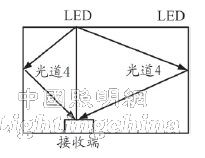
Figure 2 LED diffused optical channel model
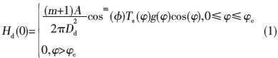
The direct line-of-sight optical channel DC gain is expressed as Hd(0), and the diffused optical channel (first reflected light) DC gain is expressed as dHref(0). Direct line-of-sight optical channel DC gain [4] is:
The DC gain of the diffused optical channel (first reflected light) is:
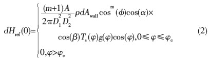
In equations (1) and (2), m is the radiation mode of the light source, A is the receiving area of ​​the photodetector, d is the distance between the transmitting end and the receiving end, the quasi-incident angle, φ is the emission angle, Ts ( φ) is the optical filter gain, g(φ) is the optical concentrator gain, and φc is the receiver viewing angle.
2 OFDMA and SC-FDMA modulation technology
Through the analysis of the indoor visible light communication channel, multi-path effects are easily caused in indoor visible light communication, and the introduction of OFDM (Orthogonal Frequency Division Multiplexing) technology can effectively resist multipath interference, so that the interfered signal can still be reliably received, and its signal The band utilization rate is also greatly improved [5]. The system model is shown in Figure 3.

Figure 3 OFDM system model block diagram
Since OFDM has a characteristic of high intrinsic peak-to-average power, there is distortion in the OFDM signal. In visible light communication systems, higher envelopes can affect vision and also affect the lifetime of optical devices. To overcome this shortcoming, we modify the uplink OFDM technology. The modified OFDM technology version is called single carrier FDMA (SC-FDMA technology), as shown in Figure 4.

Figure 4 SC-FDMA system model block diagram
The SC-FDMA technology adopts the principle of single-carrier modulation and frequency domain equalization, has the same performance as the OFDM system and basically the same overall structure, but has a lower peak-to-average power ratio. They are continuous subcarrier transmissions, not parallel. Compared to OFDM technology, this technique greatly reduces the envelope fluctuation of the transmitted waveform. Therefore, the SC-FDM signal has a PAPR lower than that of the OFDM signal.
Figure 4 includes the transmitter and receiver. It can be seen that SC-FDM has much in common with OFDM. The only difference is that the transmitter and receiver of SC-FDM use DFT discrete Fourier transform. For this reason, SC-FDMA technology is sometimes referred to as DFT extension of OFDM technology. Currently, the SC-FDMA subcarrier mapping mode is divided into two categories, namely, distributed and localized [6], as shown in FIG. 5.
In the distributed subcarrier mapping mode, the DFT output of the input data uses the unused subcarriers to occupy the entire bandwidth with discontinuous zeros. Interleaved SC-FDM (IFDMA) is an important special case of distributed SC-FDMA. In localized subcarrier mapping mode (localized SC-FDMA, LFDMA), the output and input data of DFT are continuous. Subcarrier occupancy.
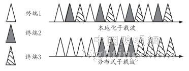
Figure 5 SC-FDMA subcarrier mapping mode