In the maintenance of modern automobile electronically controlled engines, there are often some seemingly incomprehensible fault phenomena. Due to the influence of inertial thinking in traditional fault diagnosis, maintenance operators often feel at a loss, and it is difficult to consider judgments from the correct direction of thinking. Quickly and accurately find the true root cause of the failure. According to the examples in product development, from the perspective of after-sales maintenance and solving problems, this paper conducts continuous research and analysis on the causes of abnormal misfire of electronically controlled engine shifting of LZW6360BI1 Euro III emission standard, and discusses the use of general GMS problem red cross (×) The method uses the oscilloscope, the digital recorder and the X431 electronic control detector to perform voltage signal interference analysis to realize fast and accurate diagnosis of some difficult faults of the electronically controlled engine.
This article refers to the address: http://
In order to continuously improve the product quality and performance of the vehicle and meet more stringent relevant emission regulations and noise control requirements, in June 2005, SAIC-GM-Wuling Automobile Co., Ltd. upgraded and upgraded the engine electronic control system for the best-selling LZW6360BI1 minibus. This model matches the LJ462QEI1 electronically controlled engine and uses the electronic control management system of Delphi MT20U (Delphi II). The main differences between the electronic control system before and after the upgrade are shown in Table 1.
First, the phenomenon of failure
After the first batch of test vehicles passed the road test of 30,000 km in May 2005, the performance of each test was in line with the product design requirements, and there was no abnormality. However, in the subsequent small batches of specific test users, the feedback is gradually changed when there is a red light such as a shift or when the air is coasting. The fault performance has certain special characteristics: the vehicle can start normally, there is no other abnormal condition during driving, the engine fault indicator light is not bright before the flameout, and there is no fault code. The engine can start immediately after the engine is turned off, and other performances such as dynamics There is no abnormality in acceleration, economy, etc., and the fault appears to be intermittent from time to time. It is difficult to reproduce the short-term test failure phenomenon.
Second, fault diagnosis
In response to the special performance of this fault, the relevant departments of SGMW initiated the red cross (×) troubleshooting method of the general GMS problem to analyze and study the problem.
According to the operation requirements of the red cross (×) troubleshooting method, the problem is first defined, the possible causes of the problem are listed, and the red cross (×) is excluded according to the relevant reasons, and then the remaining possible causes are listed as follows. A round of problem definition, such a cycle, gradually narrowing the root cause of the problem, in order to achieve efficient and rapid problem solving.
(1) Problem definition 1
The reason for the reason that the throttle is decelerated and the gear is shifted to the idle speed when the throttle is decelerated and the gear is decelerated when the gear is turned into the idle speed is shown in Table 1.
(2) Problem definition 2
The electrical part failure analysis of the electrical part is shown in Table 2.
(3) Problem definition 3
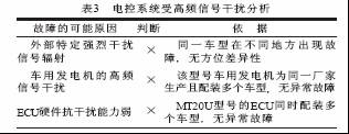
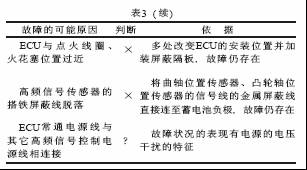
The electronic control system is interfered by high-frequency signals. The high-frequency signal interference analysis of the electronic control system is shown in Table 3.
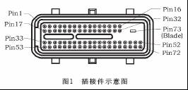
After several times of troubleshooting, the root cause of the problem is gradually narrowed down. The corresponding lines of Pin17 and Pin18 pins that enter the ECU's normally-on Power Supply from the engine harness of the faulty vehicle are two red wires ECU17# and ECU18#, as shown in Figure 1. Show.
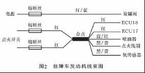
Disassemble the engine harness assembly, find the wiring junction along the two red normally-on power wires in the direction of the power interface, and find that it is connected with the ignition coil and the fuel supply line of the injector, as shown in Figure 2.
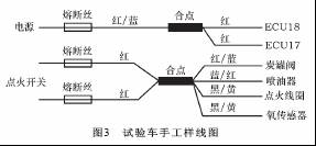
The engine harness of the first batch of test samples was a manual sample line, which was disassembled and analyzed. It was found that the corresponding ECU17# and ECU18# constant power lines were connected separately, as shown in Figure 3.
Third, failure analysis
The primary power supply line of the ignition coil in the engine harness assembly is connected to the ECU17# and ECU18# normally-on power lines entering the ECU, causing high-frequency voltage signals generated during the operation of the ignition coil to interfere with the idle stepping motor, and the electronic control system The misoperation makes the idle stepping motor control step number smaller, and the working condition when the vehicle shifts into the idle speed is the most sensitive point of the idle stepping motor operation, thus causing the failure to occur. The following analysis is performed from the comparison of the results tested with the oscilloscope and the data logger.
The oscillating record of the fault car idle speed stepping motor signal and the ignition coil ignition voltage signal is shown in Fig. 4. The oscillographic record of the idle speed stepping motor signal and the ignition coil ignition voltage signal of the test sample is shown in Fig. 5.
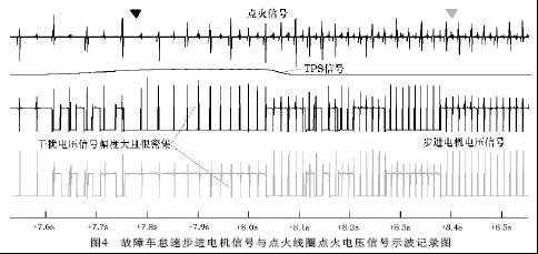
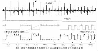
From the comparison of the above two oscillographic recordings, it can be clearly shown that the voltage interference signal of the faulty vehicle ignition signal is large and dense, which greatly exceeds the anti-interference ability range of the electronic control system, resulting in the occurrence of faults.
Fourth, troubleshooting and verification
The correct engine harness assembly for mass production on 8 faulty vehicles was continuously tracked by the 20,000 km road test, and no fault recurrence of the abnormal shift of the shift was found.
The electronic control management system used in the electronic control engine of the automobile is often sensitive to electromagnetic signal interference, and the high-frequency electromagnetic signal generated when the ignition coil and the injector are working can form a strong circuit network interference, so whether in product development or In application maintenance, attention must be paid to the independent reliability of the ECU's normally-on power line to avoid connection with the power control lines of other components.
Ac Power Adapter,Ac 3 Amp Power Adapter,75W 48V 5A Power Adapter,Catv Power Adapter
Ninghai Yingjiao Electrical Co., Ltd. , http://www.yingjiaoadapter.com