**How to Extend the Performance of Low-Voltage Precision Op Amps for High-Voltage High-Side Current Sensing Applications**
**Foreword**
In high-side current sensing applications, specialized devices that can handle extended common-mode voltages are typically used. However, these dedicated components often come with their own limitations. What happens when the common-mode voltage exceeds 100V? Is it still possible to accurately measure the current? Classic 5V op amps might seem unsuitable for such tasks at first glance. But with just a few external components, we will see that low-voltage amplifiers can be effectively used to detect current without any common-mode voltage restrictions.
**Schematic and Description**
The main goal of this application is to measure the current controlled by an industrial motor operating at 150V, as shown in Figure 1. This is achieved using a shunt resistor. To accurately measure small currents, a 5V precision op amp is employed.
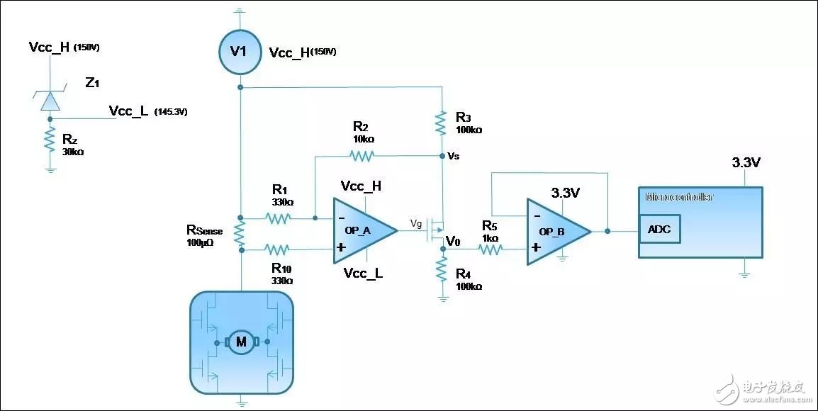
Will the 150V input damage the op amp? If the V1 voltage is used to generate the positive supply (Vcc_H) of the first operational amplifier OP_A, it won’t. A Zener diode (BZT52C4V7S) with a breakdown voltage of 4.7V is used to create the negative power supply (Vcc_L) for OP_A. In this setup, the op amp operates at 4.7V, with Vcc_L ranging from 145.3V to Vcc_H at 150V.
Resistor Rz biases the Zener diode (~5mA) and provides a path for the op amp’s bias current (~40μA). The voltage Vsense, which results from current flowing through Rsense, is then amplified by resistors R1, R2, R3, and R4.
The P-MOSFET (BSP2220) generates a precision output current proportional to the current through Rsense. The voltage Vo, relative to ground, created by resistor R4, is proportional to the high-side current. The first-stage voltage output is given by Equation 1:
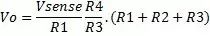
(1)
The second operational amplifier, OP_B, is used to buffer the Vo voltage. Resistor R5 is added to protect the inherent anti-static diode of OP_B from potential high-current damage during startup.
The maximum current consumed by the motor control is 100A. With a shunt resistor of 100μΩ, the largest Vsense is 10mV. The maximum output voltage depends on Vsense and the current through R4. Since this signal is processed by the microcontroller’s ADC, the maximum output voltage Vo must not exceed 3.3V.
To ensure proper system operation, component values must be carefully selected. The primary goal is to work with a low |Vgs| to prevent the output of OP_A from saturating. Keeping the low current Ids in mind, a high value for R4 was chosen.
To avoid op-amp saturation, the gain associated with OP_A, determined by the R2/R1 ratio, should not be too high. A balance must be struck when selecting component values, following Equation 2:
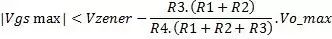
(2)
Where Vgmax is the gate-source voltage required for the transistor, and Vzener = Vcc_H - Vcc_L.
Now let's look at the accuracy of the system. Inaccuracy mainly comes from resistor mismatch and amplifier offset.
**Error Analysis**
**Resistance Mismatch**
Assuming perfect resistor matching, Equation 1 gives the output voltage. However, in reality, resistors have tolerances. The gain error due to resistor mismatch is given by:

(3)
Where εR is the precision of any resistor, and εRshunt is the accuracy of the shunt resistor. From Equation 3, we see that the effect of R2 on the error is greater than that of other resistors. Therefore, R2 should be as low as possible (e.g., 10kΩ). Also note that for gain, the sum of R1 and R3 should be high and unbalanced, while R1 should be very low to suppress noise.
**Vio's Influence**
Another source of error is the input voltage offset. In this application, the TSZ121 (a chopper amplifier) was chosen because its Vio is extremely low—only 8μV over temperature changes. When measuring very small currents, this offset becomes significant.
Considering the transfer function, Vio can be expressed as:

(4)
Where Vio1 is the input offset of the first op-amp (OP_A), and Vio2 is the input offset of the second op-amp (OP_B). Because the TSZ121 has a very low input offset voltage, Vio2 is negligible.
**Total Error**
To understand the total error of the output, we consider both resistor mismatch and op-amp offset. Finally, the output voltage can be expressed by Equation 5:
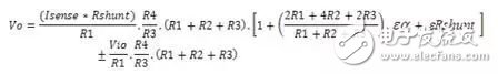
(5)
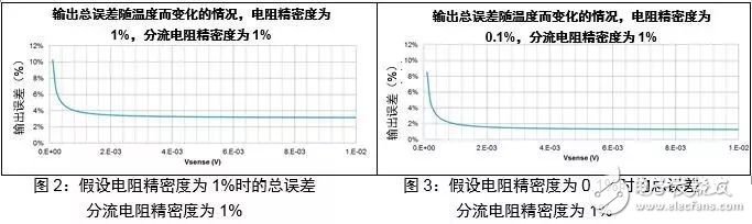
The graphs in Figures 2 and 3 show the expected maximum error as a function of temperature, taking into account the shunt accuracy.
**Conclusion**
Dedicated amplifiers are typically used for high-side current sensing. However, in applications where the common-mode voltage exceeds 70V, we found that conventional 5V op amps can also be used effectively. We demonstrated that a precision op amp like the TSZ121 can be used to detect high-side currents, along with a Zener diode to operate within the 5V range and level-shifting transistors.
We considered errors caused by resistors and amplifiers. To improve current measurement accuracy, we recommend using resistors with a precision of 0.1%.
Thank you for your interest in this content.
THANKS!!!
Lcd Tonch Screen For Iphone X,Lcd Touch Screen For Iphonexr,Lcd Display For Iphonexr,Mobile Lcd For Iphone Xr
Shenzhen Xiangying touch photoelectric co., ltd. , https://www.starstp.com