A voltmeter is an essential measuring instrument used to determine the voltage across a circuit or component. It typically consists of a permanent magnet, a coil, and other internal components that allow it to function as a precision tool. The key characteristic of a voltmeter is its high internal resistance, which makes it behave almost like an open circuit when connected in a circuit. This ensures that it does not significantly affect the operation of the circuit being measured.
In junior high school laboratories, the most commonly used voltmeters have ranges of 0–3V and 0–15V. This article provides a detailed explanation of how a voltmeter works, along with its technical specifications, structure, and classification. Let’s explore these aspects in more depth.
**Voltmeter Technical Parameters**
1. Frequency response range: 10Hz – 10MHz
2. Basic accuracy: ±2%
3. Input resistance and capacitance:
- For 1mV – 300mV: ≥8MΩ, ≤40pF, ≤100V
- For 300mV – 300V: ≥8MΩ, ≤20pF, ≤600V
4. DC output voltage: -1V (every 10 scale)
5. General technical indicators
6. Operating temperature and humidity: 0°C – 40°C, ≤90% RH
7. Power requirements: 198V – 242V AC, 47.5Hz – 52.5Hz
8. Power consumption: ≤6VA
9. Dimensions: 240mm × 140mm × 280mm
10. Weight: Approximately 2.5kg
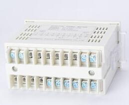
**Voltmeter Structure**
The design of a voltmeter is based on the principle of high internal resistance. When connected in parallel with a component or power source, it measures the potential difference without drawing significant current. In a parallel circuit, the voltmeter is connected alongside other devices, and it measures the voltage across them.
Inside the voltmeter, there is a permanent magnet and a coil. When current flows through the coil, it generates a magnetic field, causing the coil to rotate due to the interaction with the magnet. This rotation moves a pointer, indicating the voltage level. The current that can pass through the meter is very small, and the voltage it can withstand is also limited. To measure higher voltages, a large resistor is connected in series with the meter head, allowing the voltmeter to handle larger voltages while keeping the current through the meter low.
**Classification of Voltmeters**
1. **DC Voltmeters**
These are based on magnetoelectric or electrostatic mechanisms. A magnetoelectric voltmeter uses a small ammeter in series with a resistor to increase the range. For example, a 50μA meter can be turned into a 250V voltmeter by adding a resistor with a total resistance of 5MΩ. High internal resistance is crucial for minimizing the impact on the circuit.
2. **AC Voltmeters**
These use rectifier meters, electromagnetic meters, or electrostatic meters. Most AC voltmeters are made by connecting a small-range ammeter with a resistor in series. They are suitable for frequencies up to several kilohertz but require careful calibration for non-sinusoidal waveforms.
3. **Digital Voltmeters**
These convert the measured voltage into a digital signal for display. They are accurate, easy to read, and suitable for a wide range of environments. They often include features like noise filtering and protection against voltage spikes.
**How a Voltmeter Works**
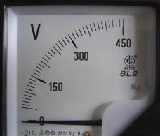
Traditional analog voltmeters operate based on the magnetic effect of current. When current flows through the coil, it creates a magnetic field that interacts with the permanent magnet, causing the coil to rotate. This movement is transferred to a pointer, which indicates the voltage on a scale.
To prevent damage, a high-value resistor is added in series with the meter. This limits the current passing through the coil, allowing the voltmeter to measure higher voltages safely. The symbol for a DC voltmeter includes a “—†under the “V,†while an AC voltmeter uses a “~.â€
**Voltage Measurement Principle**
When measuring voltage, the voltmeter is connected in parallel across the component or power supply. Current flows through the meter, generating a magnetic field that causes deflection. The greater the voltage, the more the pointer deflects, providing a direct indication of the voltage level.
**Routine Maintenance of Voltmeters**
1. Always check the polarity and range before use.
2. If the pointer moves beyond the scale, stop immediately and correct the connection.
3. After measurement, disconnect the power and store the meter in a dry, cool place.
4. For sensitive meters, short the terminals to protect the internal mechanism.
**Usage and Maintenance Tips**
- Connect the voltmeter in parallel with the circuit.
- Ensure the internal resistance is much higher than the load resistance.
- For DC measurements, connect the negative terminal first.
- Change the range only after disconnecting the meter from the circuit.
By following these guidelines, users can ensure accurate and safe operation of their voltmeters in various applications. Whether for educational purposes or industrial use, understanding the principles and proper handling of a voltmeter is essential for reliable voltage measurement.
Other Steel Structures
Steel Structures can be used in many industries such as foundation reinforce, electric power transmission structures and tubular scaffolding, etc.
A flange can also be a plate or ring to form a rim at the end of a pipe when fastened to the pipe. A blind flange is a plate for covering or closing the end of a pipe. A flange joint is a connection of pipes, where the connecting pieces have flanges by which the parts are bolted together.
Although the word flange generally refers to the actual raised rim or lip of a fitting, many flanged plumbing fittings are themselves known as 'flanges':
There are many different flange standards to be found worldwide. To allow easy functionality and interchangeability, these are designed to have standardised dimensions. Common world standards include ASA/ASME (USA), PN/DIN (European), BS10 (British/Australian), and JIS/KS (Japanese/Korean). In the USA, ANSI stopped publishing B16.5 in 1996, and the standard is ASME B16.5
Steel Structures Carport,Substation Steel Structure Fabrication,Peb Steel Structure,Light Steel Structure
Yixing Steel Pole International Trading Co., Ltd , https://www.yx-steelpole.com