First of all, it's important to understand the concept of a 51 MCU minimum system. This system refers to the most basic configuration required for a 51 microcontroller to operate effectively. As shown in Figure 2.1.1, the minimum system typically consists of three main components: the microcontroller itself, a crystal oscillator circuit, and a reset circuit.
The crystal oscillator plays a crucial role in the single-chip system. It generates the clock frequency that is essential for the microcontroller to execute instructions. All operations within the microcontroller are synchronized with this clock signal. The higher the frequency of the crystal oscillator, the faster the microcontroller can process instructions. Without a stable clock source, the microcontroller would not be able to run any program. When the microcontroller is active, it fetches instructions from ROM one by one and executes them step by step. Each time it accesses memory, it completes a machine cycle, which is the fundamental timing unit. A machine cycle consists of 12 clock cycles. For example, if a 12MHz crystal is used, each clock cycle lasts 1/12μs, making one machine cycle equal to 1μs.
The crystal oscillator circuit usually includes a quartz crystal, load capacitors, and internal circuitry. The principle behind its operation is based on the vibration of the quartz crystal, which converts electrical energy into mechanical energy and vice versa. This oscillation provides a stable and precise frequency signal, acting like a built-in clock for the microcontroller. Two 30pF capacitors are commonly used to help stabilize the oscillation and ensure proper resonance. If the capacitance values differ too much, it may lead to instability or even failure of the oscillator to start.
Internally, the microcontroller has a high-gain inverting amplifier connected between pins XTAL1 and XTAL2. When external components like the crystal and trimming capacitors are connected between these two pins, they form a self-excited oscillator, which serves as the clock source for the microcontroller.
The reset circuit is another essential part of the 51 MCU system. Its primary function is to return the microcontroller to its initial state when power is applied or during unexpected voltage fluctuations. A typical reset circuit includes a capacitor connected to the VCC pin and a resistor connected to ground. When power is turned on, the capacitor charges slowly, creating a delay that allows the microcontroller to initialize properly. In addition, the reset circuit also monitors the power supply during normal operation. If an abnormal voltage is detected, a forced reset is triggered, ensuring the microcontroller starts from a known state.
Now, let’s discuss why low-level LED lighting is often used in 51 MCU projects. The I/O ports of the microcontroller have a strong current sinking capability, meaning they can easily drive LEDs when set to a low level. Most LEDs are designed to light up when a low voltage is applied, which also helps reduce interference. Driving an LED at a high level can cause instability due to limited output capability, even with pull-up resistors. Using a low-level LED simplifies the design and makes the control code more straightforward. Additionally, it avoids issues caused by the high-level state after a power-on reset.
One thing to note is that even if the while(1) loop is removed from the code, the LED may still remain lit because the program already sets the LED to a low level. This means the LED will stay on without the need for the infinite loop.
Finally, when drawing the circuit diagram, it might appear that the LED lights up in Proteus simulation. However, in reality, this isn't possible unless the EA pin is properly configured. The EA pin determines whether the microcontroller uses on-chip or off-chip program memory. If this pin is set to a low level, it selects the external memory. To use the internal program memory, the EA pin must be connected to a high voltage.
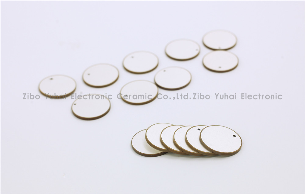
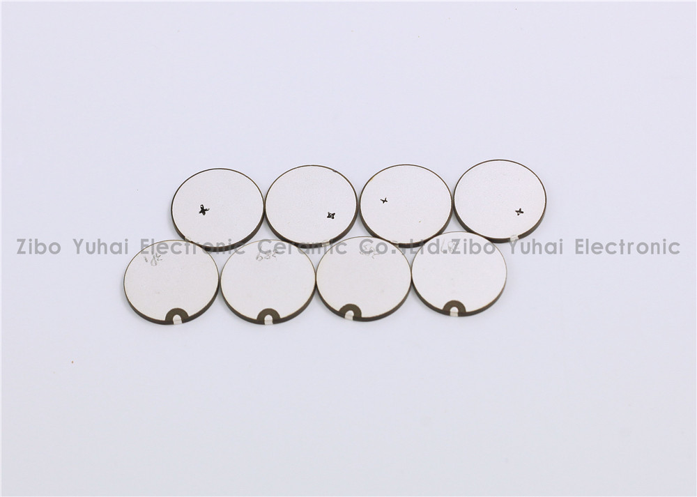
Piezoelectric Discs For Flowmeter Sensor
Piezoelectric ceramic disc
Quick delivery
High performance
Application: flow meter measurement
There are many kinds of USF used in closed pipeline according to the measuring principle, and the most commonly used are propagation time method and Doppler method. Among them, time difference ultrasonic flowmeter is used to measure fluid flow by the principle that the time difference of sound wave propagating downstream and countercurrent is proportional to the velocity of fluid flow. It is widely used in raw water measurement of rivers, rivers and reservoirs, process flow detection of petrochemical products, water consumption measurement of production process and other fields. According to practical application, time-difference ultrasonic flowmeter can be divided into portable time-difference ultrasonic flowmeter, fixed time-difference ultrasonic flowmeter and time-difference gas ultrasonic flowmeter.
Ultrasonic flow-meters use at least two transducers aligned so that ultrasonic pulses travel across the flow of liquid or gas in a pipe at a known angle to the flow.
Technical data:
Electromechanical coupling coefficient Kp: > 0.62
Dielectric Loss tg δ: <2%
Nominal Piezo discs for ultrasonic flowmeter:
OD14.2*1MHz PZT-51
OD14.6*1MHz PZT-51
OD15*1MHz PSnN-5
OD15*2MHz PSnN-5
OD20*1MHz PSnN-5OD20*2MHz PSnN-5
OD15*1MHz PZT-51
OD15*2MHz PZT-51
OD20*1MHz PZT-51OD20*2MHz PZT-51
Size, Frequency and Electrode on request.


Piezoelectric Ceramic Disc,Piezoelectric Disk Flow Meter,Piezoelectric Flow Sensor,Piezo Discs Flowmeter
Zibo Yuhai Electronic Ceramic Co., Ltd. , https://www.yhpiezo.com