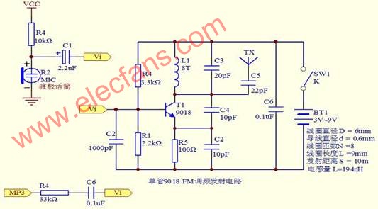
The wireless FM audio repeater can modulate the audio signal into a high frequency signal and receive it with an FM radio within a certain distance. Wireless audio repeaters are widely used in wireless headsets, car MP3 transponders, conference broadcasts, buildings and park broadcasts. The simplest wireless audio repeater can be constructed with only one transistor. The figure above shows a single tube audio FM transponder
The above figure uses a triode 9018 to form an oscillator. The audio signal is input from the base of the triode, and the frequency modulation is achieved by the varactor characteristics of the BE junction. Although the circuit is simple, the sound quality is very poor, the stability of the oscillating circuit is very bad, and the change of the voltage, the appearance of the human body or the metal object near the antenna will change the oscillation frequency and cause the instability of the receiving end. Moreover, the circuit can only transmit mono audio, and users cannot hear high-quality stereo music.
More complex stereo transponders use integrated circuits, the most commonly used is the BA1404 from RoHM. The circuit set integrates a stereo encoder that produces a 19 kHz stereo pilot signal that is transmitted with the audio. If the radio has stereo decoding, you can demodulate stereo music. The application circuit of BA1404 is shown below: 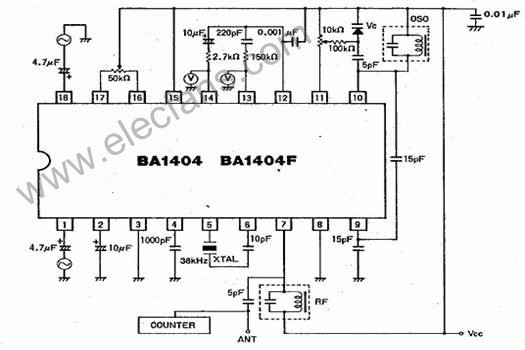
Figure 2 BA1404 application circuit
Compared with the single-tube transponder, the BA1404 can not only transmit stereo signals, but also improve the sound quality. However, the resolutions and frequency response are still not ideal. The sound quality of the BA1404 still has a considerable gap in enjoying high-quality music. Since the BA1404 still uses the LC oscillator internally, the stability of the frequency is still not good enough, and the phenomenon of frequency drift is easy to occur. There are quite a few car audio transponders or wireless earphones on the market that are sold on the market.
To create a broadcast-quality audio FM radio transmitter with very stable frequency, you need to use complex techniques such as digital audio pre-processing and frequency synthesis. Due to cost and complexity, these technologies are usually only used on radio stations, which are difficult for ordinary users to accept.
Is it a high-stability, Hi-Fi-quality audio transponder that has no chance with ordinary users? The wireless audio forwarding module VMR6512 developed by Beijing Ruiyufei Technology Co., Ltd. solves the contradiction between cost and sound quality and frequency stability, so that everyone can enjoy the broadcast quality at a very low cost.
The figure below is an internal block diagram of the VMR6512 wireless audio modulation module. 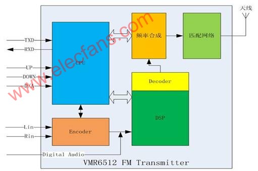
Figure 3 VMR6512 wireless audio repeater block diagram
The VMR6512 wireless audio forwarding module has the following features:
· Broadcast quality sound l
· Fully integrated package, no need to work with any external components
·The audio is processed by DSP, which guarantees high sound quality.
·Using frequency synthesis technology, the oscillation frequency is highly stable
·Output power is adjustable up to 115dBuVl
· The frequency range is 88.0MHz-108.0MHz, and the low end can be extended to 76.0MHzl according to requirements.
·Can input analog audio or digital audio
· With external UART interface, it can be easily controlled by external CPU or PC.
· Provide frequency setting UP/DOWN input for easy independent use
This module can be applied to:
·Hi-Fi wireless headset l
·Car MP3 audio repeater l
·Wireless microphone l
·Conference broadcast system
·Building music player l
·Park music play l
·Audio visual equipment accessories l
·Campus radio station l
The entire module is controlled by a CPU inside the VMR6512. The external processor can communicate with the module through the UART serial port, and set the frequency, transmit power, and interface mode of the module. In addition, the module provides two pins, UP and DOWN, for frequency adjustment without an external CPU or control serial port. The default power-on transmit frequency of the module is 100.0MHz. For each low-level pulse on the UP or DOWN pin, the transmit frequency is increased or decreased by 0.1MHz. If you keep low on both pins, the transmit frequency changes every 0.3 seconds.
The audio signal interface can be a normal analog audio input or a digital audio input. The analog audio is first converted to a digital signal by an audio A/D converter and then processed into the DSP. Digital audio provides three interface modes, such as I2S, left-justified and DSP, which can be seamlessly connected to all codecs or DSPs.
After the audio signal is digitized, the DSP processes the signal, pre-emphasizes, and generates pilots. Because it is processed in the digital domain, it has the advantage that analog circuits can't match, providing a prerequisite for high sound quality.
The module also integrates an automatic gain control (AGC) function. When the input audio exceeds a certain threshold, the AGC automatically attenuates the audio signal to avoid distortion. When the audio signal is below a certain threshold, the AGC circuit will amplify the audio signal to a certain extent, thereby ensuring that the receiving end always has a suitable volume output.
The signal processed by the DSP is then subjected to D/A conversion and sent to a high frequency modulator for FM modulation. The high frequency signal is generated by frequency synthesis. The frequency can be adjusted in steps of 10KHz. The frequency range is continuously adjustable from 88.0MHz to 108MHz. If there is special need, it can be extended to 76.0-108.0MHz. The frequency offset of the FM modulated signal can also be adjusted precisely, but it is usually not recommended to set it yourself. The output FM signal has a maximum power of 115dBuV and an open area with a transmission distance of 50 to 60 meters.
The figure below shows the shape and pins of the VMR6512: 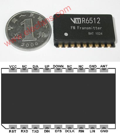
Figure 4 VMR6512 module outline and pin description
The VMR6512 module is only 25mm x 15mm x 3.8mm (L x W x H) and can be easily embedded in small devices such as wireless headsets and car MP3 audio repeaters.
The figure below shows the component symbols and pin descriptions of the VMR6512: 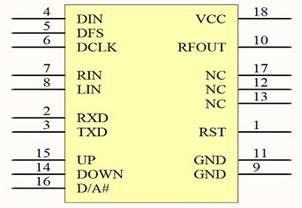
Figure 5 VMR6512 component symbol
Table 1 VMR6512 pin description
This article refers to the address: http://

Table 2 Related parameters of VMR6512

The following figure is a reference design circuit diagram of the VMR6512: 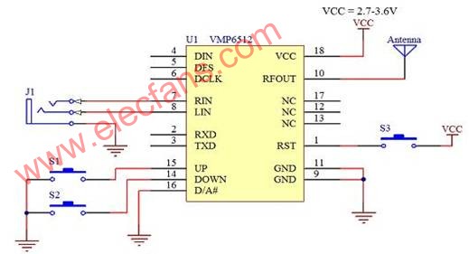
Figure VI VMR6512 reference design circuit
The reference design above is based on the design of the VMR6512 stand-alone mode of operation. Among them, S1 and S2 are used to adjust the frequency increase and decrease, respectively. S3 is used for the Reset of the entire module. The antenna uses a 75cm length of wire to get better results.
Of course, the VMP6512 can be controlled by a single-chip microcomputer or a PC, and the digital signal can be connected, which can further improve the flexibility of the transponder and obtain higher sound quality. How to control the VMR6512 through the serial port is not described here.
In general, the launch distance of the VMR6512 can reach more than fifty or six meters in the open area (depending on the antenna and radio sensitivity), which is sufficient for most needs. In some special applications, if you need to transmit a longer distance, you can use VMR6512 to cooperate with another product of Beijing Ruiyufei Technology Co., Ltd. - VMR6700 high-frequency power amplifier to extend the transmission distance to more than 1.5 kilometers. Of course, this requires permission from the relevant authorities.
The VM Series modules are packaged in high temperature resistant materials and can therefore be soldered using reflow soldering. It is also very convenient to solder with an electric iron in amateur conditions. Prepare a pointed soldering iron and some fine solder wire (best 1mm or less). Apply some flux to the pad first, then place the module in the correct position so that the pins on the module correspond to the pads one by one. Place the solder wire in the half-hole notch and gently touch the solder wire with a soldering iron. The solder will melt quickly and the half-hole pads of the module will be firmly soldered to the pads on the bottom plate. The operation of the welding is shown in the figure below: 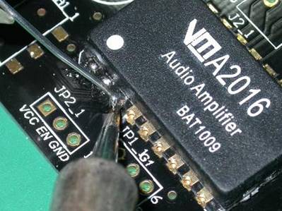
Figure 7. Manual soldering of VM series modules
PTFE Fabric With Silicone Adhesive
Strong Adhesive Tape,Silicon Tapes,Silicone Fabric,PTFE Fabric With Silicone Adhesive
TAIZHOU YAXING PLASTIC INDUSTRY CO., LTD , http://www.yaxingptfe.com