First, what is the RF induction lamp?
We call the electromagnetic induction electrodeless lamp with a working frequency of 13.56MHz as the RF electrodeless lamp to distinguish it from the high-frequency electrodeless lamp (2.65MHz) and the low-frequency electrodeless lamp (230KHz) that have been supplied to the market. The RF induction lamp operating at this frequency has many excellent electrical properties due to its high frequency, and will definitely replace the high frequency and low frequency induction lamps, making it an ideal source for future outdoor and indoor lighting.
Second, what are the advantages of RF induction lamps?
13.56MHz is a widely used frequency, such as: long-distance radio frequency identification technology, radio frequency card, hospital radio frequency thermal therapy equipment, etc., it can be seen that this is an open frequency point, the EMC index of this frequency is relatively loose More, its use is safer, important equipment in various fields will not use this frequency point, and it will not be confused by some devices that are unclear. The operating frequency of the RF electrodeless lamp is much higher than that of the high-frequency electrodeless lamp and the low-frequency electrodeless lamp, so that the power supply can be made relatively small, and the coupling efficiency of the electromagnetic wave and the lamp will be higher due to the working frequency entering the RF band. The coupling coil is expected to get rid of the magnetic material that consumes heat and is cumbersome and expensive, so that the transmitting coil and the power source can be matched strictly according to the requirements of the antenna emission and electromagnetic field theory. Since it has no bandwidth and is only a frequency point, the standing wave ratio can be made very low, the transmission efficiency will be high, and the lighting effect will naturally be high. The reason why the author strongly advocates the RF electrodeless lamp is that the high-frequency or low-frequency electrodeless lamp, the design and manufacture of the transmitting antenna-coupler is still following the concept of energy-saving lamp electronic ballast. Since the difference in the working principle of these two kinds of lamps is too large, it is not surprising that the electrodeless lamps have long been caught in the dilemma of low light efficiency. The energy-saving lamp emits electrons by illuminating the filament to excite the mercury ions in the lamp. This method is directly driven by the filament heating, so the excitation ability is particularly strong until the filament is blown up. It has no electromagnetic wave emission and reception problems, and only needs attention. The efficiency of the electronic ballast output choke - that is, whether its inductance is accurate and the core anti-saturation measures can be done. Nowadays, many papers discussing the coupling technology of the electrodeless lamp only involve the accuracy of the inductance of the coupler. However, in essence, in the theory and practice of electromagnetic wave emission of the electrodeless lamp, the standing wave ratio is the only key parameter that describes the efficiency of the launching system. The standing wave ratio has special test methods and test instruments, which are completely different from the inductance test. . The existence of these misunderstandings will inevitably lead to the coupling efficiency of the electrodeless lamp power supply and the lamp is too low, and the coupler has a serious reflection on the emitted electromagnetic waves, and also has a large anti-phasing damage to the power tube. At the same time, we installed the latest planar transformer in the RF induction lamp power supply. Compared with the size of the transformer, the size of the transformer has been greatly reduced. It has improved the indicators such as reducing leakage inductance, reducing loss and improving efficiency. Since the operating frequency is in the RF section, the EMI interference generated is mainly radiated interference, and we use the latest absorbing materials to suppress the radiation interference very well. A new EMC composite multi-function filter technology for transmitting interference can meet the EMC requirements of RF electrodeless lamp power supply.
Third, the anti-conduction technology of RF electrodeless lamp power supply
Since the RF induction lamp has a much higher operating frequency, the biggest drawback is that EMC interference becomes easy, which must be taken seriously.
1. The use of electromagnetic interference filter: The electromagnetic interference filter is mainly used for anti-EMI interference in the circuit. EMC calls it an electromagnetic compatibility indicator, which contains two requirements: one is that the interference generated by the electrical appliance to the power grid is called EMI, which is the influence of “I am externalâ€; the other is that the interference of the power grid to the electrical appliance is called EMS, which is the "outside to me" effect, has always been concerned with EMI indicators, which is not perfect. Anti-electromagnetic interference filters work in two ways:
1) Do not allow interference signals to pass through and reflect them back to the source.
2) The interference signal is consumed in the filter.
As people learn more about electromagnetic interference filters, people are more willing to adopt the second working method.
To complete the task of anti-electromagnetic interference, because it has many benefits and the least drawbacks.
2. The new EMC composite multi-function filter with combined choke coil on the power supply end:
Inside the dedicated power supply of the electrodeless lamp, a large amount of electromagnetic interference (EMI) clutter is generated around the switch tube, the freewheeling diode, and the high-frequency transformer. These electromagnetic interference clutter will become more powerful as the operating frequency increases. Propagating outwards in two ways, that is, by conduction and radiation. At the same time, the interference clutter on the mains power grid and a large number of surge overvoltages and lightning impulses will seriously interfere with the RF electrodeless lamp power supply circuit and make it work abnormally. Generally, the conducted interference is suppressed by the EMI filter circuit, but the filter circuit cannot suppress the external EMS interference. Conventional EMI filters are generally composed of discrete components such as common mode inductors, differential mode inductors, and capacitors. They are essentially a low-pass circuit with many components and large size. The distributed inductance and distributed capacitance caused by the longer leads of the discrete components have a large influence on the filtering characteristics. Such a filter is not resistant to high voltage pulses and lightning strikes that are abundant in the above-mentioned power grid. The new common mode combination choke uses two different magnetic cores to combine the common mode inductance and the differential mode inductance. At the same time, it also brings the latest modern anti-overvoltage protection and lightning protection technology. The device combines the application to replace the discrete common mode inductor and the differential mode inductor, which can reduce the filter size and greatly reduce the influence of the distributed parameters caused by the line length, and the technical parameters of the circuit are greatly improved. The magnetic fluxes generated by such a composite filter are superimposed on each other, so that the common mode inductance is correspondingly increased. However, when the differential mode current passes through the common mode inductor, the opposite is true, and the magnetic flux cancels each other. Therefore, the differential mode inductance is small and almost zero, which is in accordance with the circuit theory. The common mode inductance exhibits high impedance for the common mode current, and the differential mode The current exhibits the requirement of an ideal filter circuit with zero impedance, which is a complete new filter against EMC interference. The common mode choke coil uses a toroidal core, which is suitable for large current and small inductance. Its magnetic circuit is longer than E and U shapes. There is no gap, and a larger number of turns can be used to obtain a larger inductance. It is also convenient, and it has the best frequency characteristics among several cores.
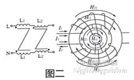
3. Fabrication of EMC composite multi-function filter: The common mode inductor uses a ferrite material special for interference suppression as the magnetic core, and the differential mode inductor uses an iron powder core that is not magnetically saturated. Figure 1 is a circuit schematic of such a filter, and Figure 2 is a schematic diagram of the winding of such a filter. We use magnetic materials produced by Sichuan Mianyang magnetic material manufacturers.
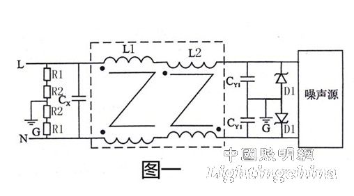
The CX value is 5μF ~ 10μF, the withstand voltage value is 275V AC value, and it is better to connect several small-capacity capacitors without polarity. R1 is a varistor, which can be used with MYL1A32K561 within 250W of power supply; R2 is a ceramic gas discharge tube, and this combination of R1 and R2 has been proved to be ideal: the non-linear characteristic of varistor is very steep, and the circulation capacity is large. The residual voltage is low and the action response is fast, but its leakage current is too large, which is easy to cause the device to age; the ceramic gas discharge tube has a freewheeling problem, and the reaction time alone is slightly longer, but its leakage current is only a few microamps negligible. The use of devices in series can each exert their advantages, and is currently widely recognized in the field of lightning protection in the forward engineering community. The general value of CY is 0.022μF ~0.047μF, and the withstand voltage value of 275V is suitable.