1 Introduction
This article refers to the address: http://
The development of clean energy has become one of the core strategies of the world in dealing with the financial crisis and economic recession. Since electric vehicles can achieve zero pollution during use, it is the most effective way to solve automotive pollution and energy problems. Hybrid vehicles have become the hotspot of new-type car development in the world in recent years due to the combination of the advantages of internal combustion engines and electric vehicles.
Lithium-ion batteries are considered to be the ideal energy source for electric vehicles because of their excellent performance. However, the driving conditions of hybrid vehicles are complex and variable, and the battery is frequently and extremely irregularly charged and discharged, which will seriously affect the battery life. Therefore, it is one of the important topics for the research and development of hybrid vehicles to propose effective battery control and management methods to extend battery life.
2 The meaning of equilibrium
In order to achieve a certain voltage, power and energy level, batteries for hybrid vehicles need to be used in series. Each unit cell is not completely identical in terms of manufacturing, initial capacity, voltage, internal resistance, and temperature. During use, a battery with a low charge amount will reach a limiting voltage prematurely, which may cause overcharging or overdischarging. Even small differences can become a non-negligible difference after a certain number of cycles. Moreover, the anti-abuse ability of lithium batteries is poor, and the application technology is still not perfect, so the probability of lithium battery abuse is greatly increased, which affects the cycle life of the entire battery. Therefore, during the operation of the hybrid vehicle, the consistency between the batteries is a very important factor in determining the battery life. To reduce the impact of this inconsistency on the lithium-ion battery pack, during the charging and discharging process of the battery pack, increase The equalization circuit.
3 equilibrium control principle
3. 1 Choice of equalization method
The battery equalization process is actually the equilibrium of the battery state of charge (SOC). For the lithium battery, the voltage of the battery changes rapidly at the high end and the low end of the SOC, and the curve in the middle part is relatively stable, and the whole curve is not linear. However, when the hybrid vehicle is working, the SOC range is about 30% to 70%. The voltage in this range is basically linear with the SOC, which means that the battery voltage can reflect the battery SOC well in this interval. The value of the voltage-to-battery equalization is an ideal balancing method for hybrid vehicles.
How to solve the problem of voltage equalization of series battery packs economically and reliably, there are many theoretical balancing methods. The current equalization control circuit is divided into two categories: energy consumption and non-energy consumption according to energy consumption.
The energy consumption type is to connect a controllable resistor in parallel with each battery cell. When the battery voltage reaches or exceeds the limit value, the resistance is turned on, and a part of the charging current is taken, so that the charging current flowing inside the battery is reduced, thereby maintaining Limit the voltage. The electrical energy flowing through the resistor is released in the form of heat, so it is called energy consumption type. This method is simple in structure and low in cost. Non-energy-consuming circuits consume less energy than energy, but the circuit structure is relatively complex and costly. In combination with the application environment of the project, considering that the battery of the hybrid vehicle is often in an irregular charging and discharging mode, and taking into consideration the economy and the space inside the vehicle, the energy-saving balance is selected here.
3. 2 control of the equalization circuit
The equalization circuit structure is shown in Figure 1.
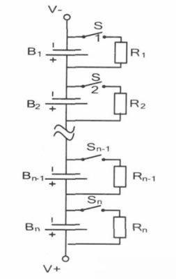
Figure 1. Structure diagram of the resistor discharge equalization circuit.
When the equalization circuit is working, the battery monitoring IC will detect the voltage of each unit battery in real time. When the inconsistent voltage of the unit battery reaches a certain value, the required equalization capacity is controlled by controlling the switching tubes S 1, S 2 , and Sn. The equalization capacity has the following relationship with the equalization time and the equalization current:
![]()
C is the equalization capacity, Ie qu is the equalization current, and t is the equalization time, where Iequ = Ud/R, Ud is the cell voltage value, and R is the discharge resistance.
The charging current in the single cell is shunted by the resistor R, and the battery with a higher voltage is discharged to the battery with a lower voltage through the resistor R. During the equalization process, the equalization current Iequ is not a constant value, and it will decrease as the voltage at the battery terminal decreases. However, since the equalization current is small, generally within 100 mA, Iequ can be considered to be approximately constant, and the equalization time is obtained by approximate calculation. For example, a battery needs a balanced capacity of 0.4 Ah, a balanced discharge resistance of 100 Ω, and a Ud of 4V, then the equalization time:
![]()
It can be seen that the calculation and control of the circuit is relatively simple, and no complicated energy storage and transfer process is required, and the equalization time is easy to grasp, and has practical application value.
4 equalization circuit design
The hardware components for equalization control of the battery mainly include an MCU control unit, a battery monitoring IC, an equalization circuit, and a power supply circuit, a temperature module, and a fan control circuit. The circuit structure diagram is shown in Figure 2. The battery monitoring IC collects the voltage of each cell terminal and sends data to the MCU in real time. The host computer communicates with the monitoring IC through the CAN bus to display the data in real time. The temperature module uses an intelligent temperature sensor that integrates the temperature sensor, peripheral circuitry, A/D converter, microcontroller and interface circuitry into a single chip that provides temperature measurement, temperature control, and data communication with the MCU.
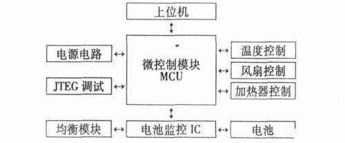
Figure 2 is a block diagram of the hardware structure of the equalization circuit.
5 Formulation of equalization control strategy
The method of balancing the balance by balancing the voltage should take into account the following points when controlling:
(1) Selection of equalized discharge resistance R. When the equalization circuit works, the high-energy battery will be released in the form of thermal energy through the discharge resistor. If the resistance temperature is too high at this time, the circuit may be out of control and there is a safety hazard. Therefore, the value of the resistor cannot be too small; On the other hand, the equalization current directly determines the equalization time. If the equalization current is too small, the equalization time will be too long to reach the equilibrium requirement, and the magnitude of the equalization current is determined by the discharge resistance. The larger the resistance value, the smaller the equalization current. Therefore, the resistance value cannot be too large. In summary, whether the resistance value can be properly selected is the key to the balance effect.
(2) Setting of the equalization voltage threshold (a). The magnitude of the voltage threshold directly determines the timing at which the equalization circuit is turned on and off. If the voltage threshold is set too large, the equalization time will be too short, the equalization effect will not be obvious, and the voltage threshold will be too small. Too long, not only consumes energy in vain, but also harmful to the battery of each battery pack. Therefore, it is necessary to analyze the charge and discharge characteristics represented by the inconsistent battery capacity, and to set the equalization threshold in combination with the application situation of the hybrid vehicle.
(3) The startup and shutdown of the equalization module. After initial power-on, the MCU periodically detects the voltage of each cell of the battery pack. Once the threshold is exceeded, the cells that need to be balanced are closed and discharged, and the switches of the other cells are turned off. After that, the MCU will periodically judge the cell voltage and re-evaluate whether it meets the equilibrium condition. If the voltage uniformity of the cells returns to within the threshold, the switching transistors of all equalization circuits are disconnected and the equalization is terminated.
6 simulation condition test
In order to simulate the effect of the battery equalization module in actual vehicle operation, the following test conditions are used and the room temperature is maintained between 10 ° C and 20 ° C. This condition test is divided into two test procedures, one is #main discharge condition, and the discharge amount is slightly more than the charge amount; the other is the "main charge condition", the charge amount is slightly more than the discharge amount, and the SOC is determined. The range of fluctuations is between 30% and 80%.
The experimental battery is a lithium manganate battery (LMi nO4), the actual capacity is 8. 6Ah, the rated voltage is 3. 6V, the internal resistance is 3. 7Ω, 12 series in series.
The battery charging curve before and after equalization is shown in Figure 3. The battery charging curve is obviously inconsistent before the equalization. The maximum voltage difference of the battery pack is about 200mV, and the corresponding capacity difference is about 20%. When charging, the high-capacity monomer will reach the threshold voltage first, so that the charging capacity of the battery is significantly reduced, only 7Ah, which greatly reduces the utilization of the battery. (b) The graph shows the charging curve after the 35-hour equalization test. It can be seen that the basic recovery is the same between the cells, the pressure difference is not more than 10 mV, and the charging capacity is expanded to 8.4 Ah. And after measurement, the discharge resistance temperature is controlled within 60 °C during the experiment, and there is no safety problem such as thermal runaway.
It can be obtained from the above experiment that this equalization method can achieve the balance of the battery SOC within 40 hours. And the circuit works stably, meets the driving requirements of hybrid vehicles, can effectively prevent the expansion of battery inconsistency, and achieve a reasonable allocation of energy.
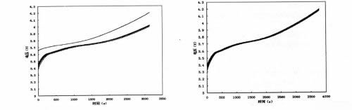
Figure 3 Comparison of charging curves before and after equalization.
7 Conclusion
The accuracy of the measurement, the stability of the system and the anti-interference ability are fully considered in the hardware design of the equalization module. In the process of formulating the equilibrium strategy, the selection of the discharge resistance, the selection of the equilibrium threshold, the start and stop of the balance are considered. The balanced test proves that the circuit works stably, can effectively solve the problem of battery imbalance, improve the use efficiency of the whole battery, and has practicality for the hybrid vehicle.
Materials: PET + Print carbon & silver + PET + 3M adhesive tape
For Pets: cell activation and basal metabolic rate are improved, the immune system is improved, and resistance is enhanced
Reach desired temperatures within minutes
Innovative far infrared heating
film, the most efficient and
reliable tools for providing heat
suitable temperature for your
pets.
")
Reptile Heater Pad,Heat Mat for Seedling,Plant Heat Mat,PTC Heat Mat for Plant
ShenZhen XingHongChang Electric CO., LTD. , https://www.xhc-heater.com