Most automotive electronic modules require voltages (5V and 3.3V) to be converted from automotive batteries. Implementing this transformation with a linear regulator results in significant power consumption, making thermal management difficult and expensive. The higher power requirements of faster processors and ASICs have driven power converters from simple, low-cost, inefficient linear regulators to more complex, efficient switching converters.
This article refers to the address: http://
Selector converter
The size of the switching converter depends on the switching frequency. As the switching frequency is higher, the power inductors and capacitors become smaller. High-efficiency converters also reduce power consumption, eliminating bulky, expensive heat sinks. These advantages make the switching converter the preferred power management for body electronics, audio and engine control modules.
Higher switching frequencies increase power consumption, but other benefits of using a switching regulator. Switching losses are significantly degraded at higher input voltages because switching losses are proportional to the square of the operating voltage. In addition, high voltage IC (40V or higher) processes are subject to overvoltage transients (such as increased losses due to load unloading). The high voltage process uses a larger form factor and a thicker gate thickness. A longer channel means a longer propagation delay. Therefore, high voltage processes are inherently slow and inefficient.
Stress condition
Any overvoltage condition that lasts longer than the thermal time constant of the electronic device can be considered a steady state phenomenon. In this case, the main concern is the continuous power consumption and the temperature rise caused.
The output set point of the voltage regulator is usually around 13.5V. The alternator voltage regulator may fail to provide full field current without regard to load or output voltage. When this happens, a voltage of more than 13.5V is added to the entire system. Usually the OEM's fail-over regulator test requirement is approximately 18V (1 hour time).
Jump start point
Another overvoltage condition is that steady state is the start of a double battery jump. This condition usually occurs when a 24V system is used to jump to start a vehicle that cannot travel. A typical OEM dual battery test requires 24V for two minutes. Reliable engine management and related security systems need to work under these conditions.
Whenever the current is interrupted, an overvoltage pulse is usually generated, so a filter, MOV (metal oxide varistor) or transient voltage suppressor is required to suppress these overvoltage transients. The ISO7637 standard specifies four basic test pulses for these induced switching transient overvoltage conditions.
Suppression system
The battery voltage cannot be fed directly into the low voltage high performance switching regulator. Instead, after the traditional input voltage limiter, a transient voltage suppressor (such as MOV) and a bypass capacitor must be added between the battery and the switching regulator. These simple circuits are designed around the P-channel MOS FET (see Figure 1). The MOSFET operates in a saturated state when the input voltage VBAT is lower than the breakdown voltage of the Zener diode Z2. During input voltage transients, the MOSFET blocks voltages above the Z2 breakdown voltage. The disadvantage of this circuit is the high number of components and the cost of the P-channel MOSFET.
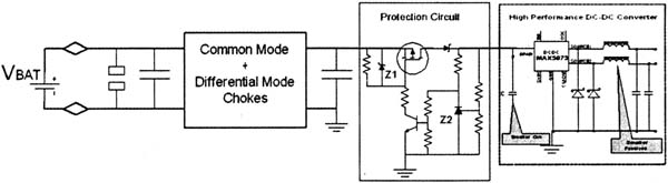
Figure 1 General voltage protection circuit with P-channel MOSFET
Another method involves an NPN transistor with its collector connected to the cell and an emitter connected to the downstream circuit. A Zener diode connected between the base of the transistor and ground clamps the base voltage, thus adjusting the emitter voltage (VBE) to be lower than the voltage V2. Although this circuit is less expensive than a MOSFET circuit, it is inefficient. In addition, the voltage drop across the transistor increases the minimum operating battery voltage that is critical during the cold crankshaft.
The third possible solution consists of an N-channel MOSFET used as a blocking component. N-channel MOSFETs are less expensive than P-channel MOSFETs. However, the circuit that drives the gate is more complex, and the voltage on the gate must be higher than the voltage on the source. Maxim's MAX6398 includes an internal charge pump that drives an external N-channel MOSFET (Figure 2). During load unloading, the MOSFET is completely turned off when VBAT is above the set limit; it remains off as long as VBAT remains above the set voltage. The MAX6398 controls the N-channel MOSFET to protect the high-performance power supply from overvoltages in the car. Connecting the downstream MAX5073 2MHz two-output buck converter reduces circuit size. The method of bonding the protector to the low voltage/high frequency power source saves space and cost compared to a high voltage converter operating at significantly lower frequencies.
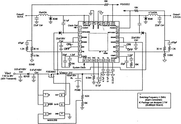
Figure 2 N-channel MOSFET switch used as a blocking device
Kitchen Hob,Gas Hobs,Gas Cooker Hob,Four Burner Gas Stove
xunda science&technology group co.ltd , https://www.gasstove.be