As a key component of modern cars, the steam harness includes thousands of assembly elements that connect various electronic systems together so that they can work together. Any small faults in the wiring harness may affect the entire system. However, in order to cope with the increasing demand for electronic systems inside vehicles, the complexity of automotive wiring harnesses is also increasing, so we urgently need to quickly and easily detect open and short circuits. Line diagnosis is very important throughout the life of the vehicle. Starting from the installation phase, diagnosing and repairing line faults can cause severe manufacturing delays. During the operation phase, diagnosing and repairing circuit faults may lead to an increase in the number of car repairs, thereby significantly increasing the manufacturer's warranty costs.
Active safety systems, including lane detection and parking assist systems (front-view and rear-view cameras), and infotainment systems (including navigation and rear-seat entertainment), are car electronic systems that people pay more attention to. For these systems to operate efficiently, the video data transmitted over the cable from any corner of the car must be able to be reliably transmitted to the driver and passengers. Cable health is essential to maintain the normal operation of these systems.
This paper presents a circuit concept that can provide reliable and cost-effective technology for diagnosis on video and audio transmission lines in automotive applications.
The circuit shown in Figure 1 can effectively detect battery short circuit (STB), short circuit to ground (STG), open circuit and short circuit faults. This circuit uses the ADA4433-1 (U1) fully integrated video reconstruction filter as part of the video transmission signal chain, and also uses the ADA4830-1 (U2) high-speed differential amplifier as the detection circuit. The ADA4433-1 has a built-in high-order filter with a -3dB cut-off frequency of 10MHz, which provides 45-dB suppression at 27MHz and an internal fixed gain of 2V / V. It has excellent video characteristics, provides overvoltage protection (OVP) and overcurrent protection (STG) on the output, and low power consumption. The ADA4830-1 provides an attenuation gain of 0.50V / V, and also provides a fault detection output flag to indicate whether there is an overvoltage condition on its input. It provides input overvoltage protection up to 18V, with a wide input common-mode voltage range and excellent ESD stability.
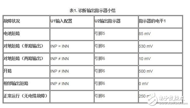
In the example circuit shown in Figure 1, U1 stands for differential output buffer, which can transmit video signals from the rear-view camera or engine control unit (ECU) to the receiver. The input is usually driven by a CMOS imaging element or video encoder. The main function of U1 is to provide active filtering function (reconstruction) and drive the transmission of video signals to the display screen through the cable. The input of U2 is connected across the output of U1 to provide the fault detection functions listed in Table 1, which will be explained in the following paragraphs.
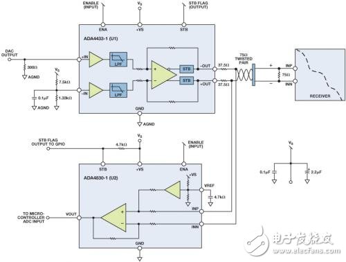
Figure 1. Line diagnostic circuit using ADA4433-1 (U1) and ADA4830-1 (U2).
Battery short-circuit fault detection
Both U1 and U2 have integrated battery short-circuit detection and STB output flags. In the event of a battery short circuit, the output flag of U2 will signal a logic low state, and the general-purpose input / output (GPIO) port of the microcontroller can easily read this signal.
Ground fault detection (single output)
Connect the positive input (INP) of U1 to the negative input (INN). The differential output between + OUT and -OUT should be 0V. If any output is shorted to ground, the differential voltage at the output of U2 should be greater than 500mV.
Ground fault detection (two outputs)
Set the positive input (INP) of U1 to 0V. The differential output between + OUT and -OUT should be approximately 1V. If both outputs are shorted to ground, the differential voltage at the output of U2 is approximately 0V.
open circuit
Set the positive input (INP) of U1 to 0V. The differential output between + OUT and -OUT should be approximately 1V. If there is a short open connection, the differential voltage generated at the output of U2 is approximately 500mV.
Adjacent output short circuit
Set the positive input (INP) of U1 to 0V. The differential output between + OUT and -OUT should be approximately 1V. If the two outputs are shorted together, the differential voltage generated at the output of U2 is approximately 0V.
Normal operation (no cable fault)
Set the positive input (INP) of U1 to 0V. The differential output between + OUT and -OUT should be approximately 1V. The differential voltage generated at the output of U2 is approximately 250mV.
Author: ADI company high-speed signal conditioning unit Marketing Engineer Don Nisbett
Hybrid Stepper Motor,Stepper Motor,Standard Hybrid Stepping Motor,Linear Hybrid Stepping Motor
Changzhou Sherry International Trading Co., Ltd. , https://www.sherry-motor.com