LED dot matrix display is widely used in shopping malls, railway stations, commercial advertisements and signal signs because of its convenient control, long service life, easy construction and low construction cost. A certain size of LED dot matrix screen is composed of multiple display units. This paper describes in detail the design and driving control of a general LED dot matrix display unit.
1 System overall design overview
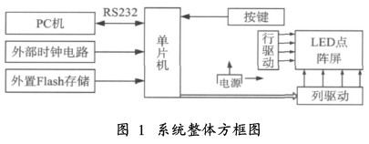
The system block diagram is shown in Figure 1. It can be seen from Fig. 1 that the PC sends commands and data from the host computer software, and transmits the data to the MCU through the serial port RS232. The MCU issues control commands to the row driver and the column driver to control the LED dot matrix screen accordingly. The external clock circuit can be used to read the display time. The external memory device is used to store the output data of the LED dot matrix screen. When the control operation is performed, the MCU can directly read the data from here, and can perform display control offline. Simple human-computer interaction with the LED dot matrix screen without pressing the PC through the buttons.
2 system hardware circuit design
The system hardware is mainly divided into two parts: LED dot matrix screen interface circuit, construction of display unit and its driving circuit; control system based on single chip mega16, used to complete data receiving and controlling LED dot matrix screen.
2. 1 LED dot matrix interface circuit
Figure 2 is the internal structure of the 8*8 LED dot matrix display. The four 8*8 dot matrix can form a 16*16 dot matrix screen for displaying Chinese characters. The 8*8 dot matrix display principle is to control the LEDs on and off by using the LEDs in the row and column. As shown in Figure 2, if you want the LEDs of row 1 and column 1 to be lit, you only need to make 1 high level and 1 low level. The LED display screen relies on such a selection of rows and columns for the transformation of various graphic characters.

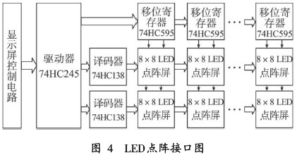
Figure 4 shows the connection mode of the LED dot matrix screen. The upper and lower half screens of the 8 8 dot matrix are connected together to form a system. This system uses a line scan method that uses two 3-wire 8-wire decoders 74HC138 to drive the upper 8 rows and the lower 8 rows of the dot matrix, respectively. In the case that the dot matrix screen is not large, the general MCU can directly drive the LED of the dot matrix, but when considering expanding to a large screen size, the I/O port of the MCU is not enough to provide sufficient driving current, as shown in Figure 3. As shown, a PNP-type 8550 triode switch circuit can be connected to the 74HC138 and the matrix interface of the dot matrix to provide sufficient current. When the 74HC138 emits a low level, the transistor Q is turned on and the LED_H outputs a high level. At this time, the I/O port only needs to provide a few milliamps of sinking current to control its on/off. If you need to expand the screen, you only need to connect the extended upper and lower half-screen LED dot matrix lines to the 74HC138.
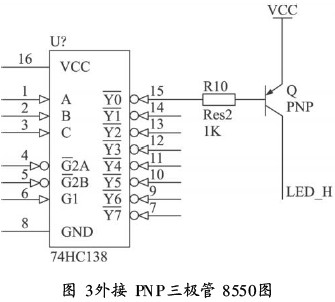
This system uses 74HC595 latch to drive control the column line, which has a 2-stage latch shift output function. As shown in Figure 3, the column line of the LED dot matrix is ​​connected to the 8-bit parallel output port of the 74HC595. The output of the data is controlled by the MCU. Using the latch output function of the 74HC595, the circuit shares the same shift clock SCK and the data latch clock. RCK, can cascade multiple 74HC595 to form the column driver circuit of the larger LED dot matrix screen. This configuration also allows grayscale adjustment through the PWM wave at the enable side of the 75HC595.