With the acceleration of urbanization, more and more urban construction and construction. In order to prevent accidents of passing vehicles and pedestrians, it is common to set up prominent construction signs on the construction site, especially at night and when it rains, snows, and dense fog. When the weather is more dangerous, it is usually necessary to turn on the warning light to ensure safety. In order to improve the warning effect, the warning light works as if it is flashing. A solar warning light is introduced in the paper. The circuit is powered by solar panels and batteries. It has two functions: manual control and light control. In the automatic control state, after the dark, the circuit can control the warning light to automatically turn on, and make it work in the blinking state, and the warning light can be automatically turned off during the day. It can also be manually controlled, and it can be operated during the day, which is easy to adjust, low in cost and convenient to use.
1 System Overview This system has two working modes: manual control and automatic control. In the manual control state, press S1, the circuit is turned on, and the warning light starts to flash, reminding the vehicle or pedestrians to pay attention. In the automatic control state, controlled by ambient light, the resistance of the photoresistor can control the on and off of the relay to control the working state of the warning light. When the daytime light is good, the resistance of the photoresistor is small, the relay is disconnected, and the warning light does not flash. When the light is dark at night, the resistance of the photoresistor becomes larger, the comparator outputs a high level, the relay is closed, and the warning light is energized to start flashing, which serves as a warning.
2 Hardware Design The system consists of four parts: power supply unit, light control unit, main control MCU unit and LED lighting unit.
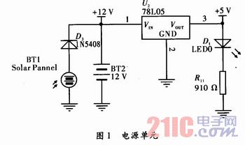
2.1 Power Supply Unit This system uses solar panels to charge 12V battery through diode 1N5403. The 12V battery is regulated by 7805 to supply power to AT2051. It is powered by battery at night or on cloudy days. The BT2 is a 12 V battery and the D1 is a power indicator. The power supply unit is shown in Figure 1.
This article refers to the address: http://
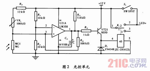
2.2 The light control unit MG1 is a photoresistor. The photoresistor is a special resistor component made by the semiconductor light guide effect. It is characterized by being sensitive to light. When exposed to light, the resistance is small and there is no light. When irradiated, the resistance value increases rapidly and is in a high resistance state. VR1 is an adjustable resistor, U21A is LM358, VT21 is 8050, and K1 is JZ-23F (4123) type relay. VR1, MG1, R21, R22, and R24 form a hysteresis comparator, and D2 is a discharge diode of the relay. The ruler 24 is a positive feedback resistor. After the resistor is introduced, the comparator has hysteresis characteristics, that is, it has inertia, and thus has a certain anti-interference ability. For example, if the resistor is removed, if the light changes to a critical state, if there is external interference. Or any small change in the input voltage near the threshold voltage will cause a jump in the output voltage, causing the relay to repeatedly pull in and the operating state is unstable. When the daytime light is strong, the photoresistor MG1 has a small resistance, a small voltage drop, a comparator output level is low, the VT21 is turned off, the relay is not turned on, and the LED lamp unit does not operate. When the night is dimly lit. MG1 dark resistance is large, up to hundreds of kΩ or more, the voltage on MG1 is higher, the comparator output is high level, VT21 is on, the drive relay is turned on, and the LED lighting unit is powered. S1 is a manual switch. If you want to work it during the day, press S1. Light control unit is shown in Figure 2.
Shown.
2.3 Master MCU unit AT89C2051 is a low voltage, high performance CMOS 8-bit MCU with 2 kB of re-writable read-only Flash program memory and 128 B of random access data memory (RAM) compatible. The standard MCS-51 command system, built-in general-purpose 8-bit CPU and Flash memory unit, is powerful with only 20 pins, of which P1 is a complete 8-bit bidirectional I/O port.
The unit adopts AT89C2051 single-chip microcomputer as the central processing chip, which makes the function modification and expansion of the system more convenient. If you need to modify the flicker frequency and time, just change the corresponding software.
RP1 is a row resistor with a resistance of 5kΩ, and R1 to R4 are current limiting resistors. The output uses four ports of P1.0 to P1.3. Since the current of the LED light-emitting unit is larger, the NPN-type medium power transistor BD435 is used for expansion at the output port. PNP-type transistors can also be used to modify the corresponding program. can. The main control MCU unit is shown in Figure 3. Use Protel 99SE to carry out the printed circuit board wiring of this circuit, with AT89C2051 as the core layout, the power input end is on the upper side, the signal output end is on the right side, the warning light printed board is made by the sensitization method, the printed board diagram and the physical object are as shown in the figure. 4 is shown.


2.4 LED lighting unit uses LED as the light-emitting unit, which has the advantages of low power consumption, high brightness, good stability and long life. The supply voltage is 12 V and consists of a total of 4 luminescent panels. The color of the LED is red and blue. Considering different LED voltage drops of different colors, each illuminating board consists of three LEDs connected in series, and five groups are connected in parallel to form one illuminating board. Each illuminating board is composed of 15 LEDs. . The principle of LED illuminating board is shown in Figure 5.

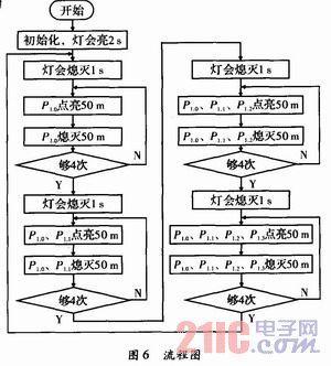
3 software design according to the visual experience, the time of illumination is better at 50 ms, after 4 flashes, pause for 1 s, and then flash in sequence. The order of flashing LED lights is LED1 flashing 4 times→LED1, LED2 flashing 4 times→LED1, LED2, LED3 flashing 4 times→LED1, LED2, LED3, LED4 flashing 4 times→LED1 flashing 4 times. The system software part is mainly composed of delay and loop, and the program flow chart is shown in Figure 6.
4 Conclusion This warning light system is applicable to urban municipal construction, road construction sites and traffic intersections, etc. It can effectively remind vehicles or pedestrians to pay attention to safety and play a warning role. The warning light system is low in cost, reliable in operation, and easy to modify and expand.
The Link Fitting is primarily used for the link of insulators and the connection of fittings. It bears mechanical load. Generally, link fittings are divided into ball eyes, socket eyes, shackles, extensive links, eye links, clevises, extensive rods, adjuster plates, towing plates, U-bolts and yoke plates. Generally, malleable cast iron and steel are used as it's materials.
All the ferrous metal should be hot-dip galvanized.

Link Fitting
Link Fitting,Link Fitting For Substation,Connecting Fitting,Link Fitting For Power Plant,Mid Span Joint,Power Line Connectors
Jiangsu Chuandu Electrical Technology Co.,Ltd. , http://www.cdepf.com