In our previous discussion on grounding techniques, we highlighted the significance of maintaining a low-impedance ground plane to provide stable current paths for both digital and analog circuits. Building upon that foundation, today we’ll delve into another critical aspect of circuit design: how to effectively use power supply decoupling to keep the power supply stable and low-impedance for integrated circuits (ICs) at various operational points.
Analog ICs like amplifiers and converters often have two or more power supply pins, while single-supply devices might connect one pin directly to ground. Mixed-signal devices, such as ADCs and DACs, may require separate power supplies for their analog and digital sections, along with additional I/O voltages. Similarly, digital ICs like FPGAs frequently operate on multiple power rails, including core voltage, memory voltage, and I/O voltage.
Regardless of the number of power pins, the datasheet specifies the acceptable range for each power supply, including recommended operating ranges and absolute maximum ratings. Adhering to these limits ensures proper functionality and prevents potential damage. However, even minor fluctuations in supply voltage—whether caused by noise or ripple, and even within the recommended operating range—can degrade device performance. For instance, in an amplifier, slight variations in the power supply voltage lead to corresponding changes in the input and output voltages, as illustrated in Figure 1.
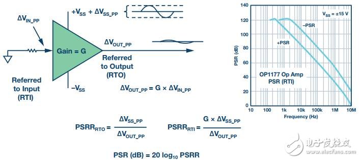
This sensitivity is typically quantified by the power supply rejection ratio (PSRR), which measures the ratio of the change in supply voltage to the resulting change in output voltage. In Figure 1, the PSRR of a high-performance amplifier (OP1177) decreases at a rate of about 6 dB per octave (or 20 dB per decade) as frequency increases. While the PSRR remains strong at DC levels, it diminishes significantly at higher frequencies, allowing more unwanted energy to couple directly to the output. If the amplifier is driving a load and there’s unwanted impedance on the power rail, the load current can modulate the power rail, introducing additional noise and distortion into the AC signal.
Even if the exact PSRR isn’t explicitly stated in the datasheet, the performance of data converters and other mixed-signal ICs will suffer from power supply noise. Additionally, power supply noise can impact digital circuits in several ways, such as reducing logic-level noise margins and causing timing errors due to clock jitter.
**Proper Local Decoupling is Essential**
A standard 4-layer PCB is usually designed with a ground plane, power plane, top signal layer, and bottom signal layer. The ground pins of surface-mount ICs are directly connected to the ground plane via vias, minimizing unwanted impedance in the ground connections. Power rails are typically routed through the power plane to reach the various power pins of the IC. Figure 2 illustrates a simplified model of an IC showing its power and ground connections.

The current generated within the IC is represented as \(I_T\). This current flows through the trace impedance (\(Z\)), producing a change in the supply voltage (\(V_S\)). As discussed earlier, depending on the PSR of the IC, this can lead to performance degradation.
To minimize sensitivity to power supply noise and ripple, the best practice is to use the shortest possible connection and directly connect the appropriate type of local decoupling capacitor between the power supply pin and the ground plane. The decoupling capacitor serves as a charge reservoir for transient currents, shunting them directly to ground to maintain a constant supply voltage across the IC. Although the loop current path passes through the ground plane, the low impedance of the ground plane minimizes any significant error voltage.
Figure 3 highlights the importance of placing high-frequency decoupling capacitors as close as possible to the IC. Otherwise, even the inductance introduced by wiring can undermine the effectiveness of the decoupling.

On the left side of Figure 3, the power pin and ground connection are short, making it the most efficient configuration. Conversely, the extra inductance and resistance in the PCB traces on the right side reduce the effectiveness of the decoupling scheme, and longer loops can create interference issues.
**Selecting the Right Type of Decoupling Capacitor**
Low-frequency noise decoupling typically requires electrolytic capacitors (usually ranging from 1 μF to 100 μF) as a low-charge reservoir for transient currents. Meanwhile, surface-mount ceramic capacitors (typically 0.01 μF to 0.1 μF) should be placed directly on the IC's supply pins to minimize high-frequency power supply noise. All decoupling capacitors must be connected directly to the low-inductance ground plane to be effective. This requires short traces or vias to minimize added series inductance.
Most IC datasheets outline recommended power supply decoupling circuits in the application notes. Users should always follow these guidelines to ensure proper device operation.
Ferrite beads, which are insulating ceramics made from oxides of nickel, zinc, manganese, or other compounds, can also be used for line filtering and decoupling. These materials are inductive at low frequencies (<100 kHz), making them useful for low-pass LC decoupling filters. Above 100 kHz, ferrites become resistive (with low Q). Their impedance depends on factors such as material, operating frequency, DC bias current, number of turns, size, shape, and temperature.
While ferrite beads aren’t always necessary, they can enhance high-frequency noise isolation and decoupling, which is often beneficial. However, you need to confirm that they won’t saturate, particularly when an op-amp drives high output currents. Once saturated, ferrites become non-linear and lose their filtering characteristics. Some ferrites may even exhibit non-linearity before reaching full saturation. Therefore, if the power stage demands low-distortion output, the ferrite should be tested when the prototype operates near this saturation region. Figure 4 shows the typical impedance of ferrite beads.

When selecting the right type of decoupling component, it’s crucial to consider non-ideal capacitive behavior due to parasitic resistance and inductance.
In summary, effective power supply decoupling is vital for maintaining stable and clean power delivery to ICs. Proper placement of decoupling capacitors and careful selection of components can significantly improve circuit performance and reliability. Always refer to the datasheet for recommended practices and test your designs thoroughly to ensure optimal results.
Bee Eyes Beam Light ,Mini Bee Eye Moving Head,Bee Eye Led Moving Head,Bee Eyes Beam Lights
Guangzhou Cheng Wen Photoelectric Technology Co., Ltd. , https://www.cwledwall.com