Differences between the two versions The DS2154 version A2 uses a 0.8µm CMOS process. The D2 version of DS2154 is a 0.6µm CMOS process.
Regardless of the DS2154 version A2 or D1, their internal registers are in a random state when powered on. The user must set all internal registers to a known state to ensure correct operation. This includes setting the test register to 00h. The most efficient initialization method is to use a routine to write 0x00 to addresses 0x00 to 0xFF.
Transmission test timing chart For ease of reference, the transmission test timing chart is given in the following figures, including the transmission test TSYNC and frame number, TSYNC and time slot number, and the relative timing relationship between TSYNC and TCLK. Note that they are the same in versions A2 and D1 (for further details, please refer to the DS2154 data sheet).
Figure 1. Relative timing between TSYNC and frame number.

Figure 2. Relative timing between TSYNC and timeslot (TS) numbers.

Figure 3. Relative timing between TSYNC and TCLK.
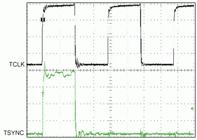
In DS2154 of D1 version, if TSYNC is configured as an input by setting TCR1.0 = 0 (TSIO = 0), the E1 SYNC signal sometimes cannot be correctly synchronized with the MSB of time slot 0 (TS0). Figure 4 shows a possible TSYNC and TCLK timing captured with an oscilloscope, which is correct for the DS2154 version A2. However, it may not be correct for the D1 version of the DS2154.

Figure 4. The relative timing between TSYNC and TCLK measured by the oscilloscope.
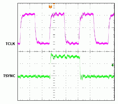
Figure 4 shows that the falling edges of TCLK and TSYNC arrive almost simultaneously. The D1 version samples the input TSYNC on the falling edge of TCLK. In order to obtain correct sampling, users need to delay TSYNC by 25ns or more. Alternatively, the TSYNC clock pulse can be widened. In this way, the sampling problem can be eliminated. The A2 version of the DS2154 has a rising edge detector to help align TSYNC and TS0. The D2 version of the DS2154 simply samples TSYNC with the falling edge of TCLK. Figure 5 shows the timing relationship between TCLK and TSYNC after widening the TSYNC pulse.

Figure 5. The relative timing between TSYNC and TCLK measured by the oscilloscope after the TSYNC pulse is widened.
Acid Filling Machine,Battery Acid Filling Machine,Acid Filling Machine Battery,Quality Acid Filling Machine
Zhijiang BSL battery technology service company , https://www.bslbatteryservice.com