Ultra-low-cost broadband intermediate impedance converter
The materials for the low-cost RF impedance conversion probe introduced in this article are readily available in the laboratory. When dealing with low-impedance circuits, impedance conversion probes can perform some very useful measurements. Including the positioning of spurious signals, the measurement of spurious signals and harmonic levels, the judgment of faulty amplifiers or faulty saw filters. When measuring the 50 impedance point of a circuit, the probe is very effective in the frequency range of about 400khz to 1ghz.
Impedance converter design
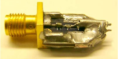
The RF impedance converter consists of a sma connector in series with a capacitor, resistor and a short semi-rigid coaxial cable in series. The semi-rigid coaxial cable serves as the probe of the impedance converter, as shown in Figure 1. The sma connector is connected to a spectrum analyzer via a standard sma cable. The converter's intermediate impedance (1k) prevents it from significantly affecting the circuit in low impedance (such as 50) circuits. In order to keep the circuit in good working condition, choose a resistor with a resistance to circuit impedance ratio of 20: 1. The selected coupling capacitor should ensure that its self-resonant frequency is the middle value of the operating frequency band, and that it exhibits a low resistance characteristic relative to the selected resistance value. This design chooses 1000pf capacitor and 1k resistor, and the package size is 0603.
Impedance converter performance
Figure 2 shows the frequency response of an impedance conversion probe operating from 400khz to 1ghz, and the flatness is 1db. The resulting measurement error is much lower than the typical error of more than 10db when dealing with failures (such as amplifier operation failures). In addition, when the coaxial cable is removed and the resistance is directly used as a probe, the maximum operating frequency of the converter can be extended to 1.9ghz. This method can reduce the resonance of the converter near 3ghz. Of course, this converter is easy to damage, but it can explain the influence of the parasitic effect of the coaxial cable on the flatness of the frequency response characteristics. The shorter coaxial cable can provide good rf performance, while the longer coaxial cable has more welding surface, which can strengthen the mechanical strength. After weighing the two, we put the coaxial cable in Figure 1 The length is selected as 11mm.
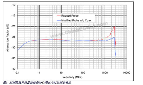
Assuming a low impedance circuit of 50 and a 1k intermediate impedance form a simple 50/1050 voltage divider, then the power level measured at the sma connector should theoretically be -26.4db lower than the power level at the probe. This point is consistent with the response curve in the frequency range of 400 khz to 1 ghz shown in FIG. 2. The frequency response in Figure 2 is the measurement result of connecting the probe across a 50 ohm resistor at the output of a calibrated signal generator. In addition, it is assumed that the 1k impedance of the probe is added to the 50 impedance of the spectrum analyzer and then connected in parallel with the 50 impedance of the circuit, so that in an ideal situation, the probe only measures -0.2db for the circuit under test when measuring the 50 load circuit Impact.
Making conversion probe
In order to assemble a conversion probe as shown in Fig. 1, first cut a small piece of printed circuit board with SMA interlayer connector and 50 microstrip transmission line. Then carefully cut several slits on the microstrip line, and weld 1000pf capacitor and 1k resistor in series to the slit. Capacitors and resistors are 0603 package. Cut another 11mm long semi-rigid coaxial cable with a diameter of 0.086 ". The center conductor of the coaxial cable exposes 2.5mm at one end and 2mm at the other end. The end where the 2mm is exposed is the probe part. The residue on the strip line is bent and soldered to the microstrip line close to the resistor, exposing the 2.5mm center conductor. Next, fill the solder between the outer side of the conductor and the metal ground to fix the coaxial cable. Use a large number of The solder fixes the coaxial cable firmly on the printed circuit board. If necessary, it can be bridged with a copper layer. Then a small length of center conductor parallel to the coaxial cable is used as the ground terminal of the probe. Finally, the probe of the conversion probe Add a small drop of solder to the ground terminal to maintain good contact with the circuit under test.
Litz Wire Typical applications are: high frequency inductor, transformer, frequency converter, fuel cell, the horse, communication and IT equipment, ultrasound equipment, sonar equipment, televisions, radios, induction heating, etc.In 1911, New England became the first commercial manufacturer in the United States to produce the Leeds line.Since then, New England has remained the world leader in providing high-performance Leeds line products and solutions to customers around the world.It is also transliterated as the "litz line".
Litz Wire
Litz Wire,Copper Litz Wire,Copper Transformer Litz Wire,High Temperature Litz Wire
YANGZHOU POSITIONING TECH CO., LTD , https://www.yzpstcc.com