Design of Intelligent Anti-theft Anti-collision Alarm System
Introduce a car anti-collision and anti-theft alarm system that combines the real-time control and data processing functions of the single-chip microcomputer with ultrasonic ranging technology and infrared sensor control and measurement technology.
Keywords: MCU; anti-theft anti-collision; alarm
Huaian 223001, China)
(2) Display mode: static continuous display;
(3) Detection of human body: the use of infrared sensors, if there is theft, can transmit the signal to the single chip in time;
(4) Alarm processing: judging the measured parameters beyond the limit, if it exceeds the limit, it will give an audible and visual alarm;
(5) Transmit and receive function: realized by anti-theft transmitter and receiver, controlled by single chip microcomputer; another remote control is used for remote control of anti-theft signal.
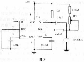
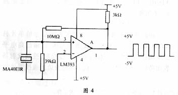
1.4 Working principle (1) The choice of sensor The automobile anti-collision system involves distance detection. According to the measurement environment and requirements, the use of ultrasonic ranging has the characteristics of high measurement sensitivity, strong penetration, fast measurement speed, and large measurement angle. It can detect objects in a large range. This system selects MA40EIS ultrasonic transmitting sensor and MA40EIR receiving sensor.
The anti-theft system uses infrared sensor TX05D, which is an "integrated" infrared transmitting and receiving device, which contains infrared transmitting, receiving, signal amplification and processing circuits, which can detect human bodies or objects in a certain range in front in a non-contact manner , And converted to high-level output. TX05D internally uses low power consumption devices and anti-interference circuits, which are stable and reliable, and have excellent performance. ?
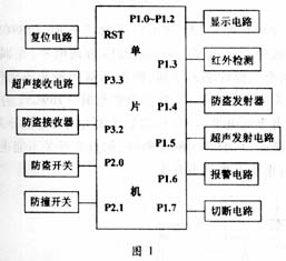
(2) Anti-collision detection This system uses the single-chip AT89C51 as the signal controller. The specific working process is as follows: the anti-collision switch is connected to the P2.1 pin of the AT89C51. When the switch is closed, the P1.5 end of the AT89C51 is set to 0 to transmit ultrasonic waves, and the counter starts counting. The ultrasonic receiving circuit receives the signal and inputs the signal to interrupt 1 (for edge trigger). At the same time when the signal is received, the counter is turned off, the count value is read out, and the distance is calculated; this distance is compared with the alarm distance. When the distance is less than the alarm distance, the distance is displayed , And AT89C51 P1.6 is set to 0 for audible and visual alarm, when it is greater than the alarm distance, no alarm.
(3) Anti-theft detection?
The effective signal is input to the single-chip AT89C51 by the infrared sensor integrated circuit. When the infrared sensor detects the human body, the high-level output passes through the inverter and is received by the single-chip microcomputer for anti-theft control. The transmitter is controlled to send out an anti-theft signal (pulse). The driver receives the signal through the remote control around him and performs corresponding treatment. Cut off the start circuit.
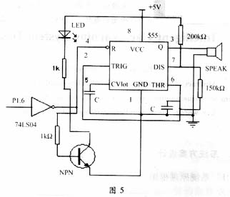
The specific working process is as follows: the anti-theft switch is connected to the P2.0 pin of the single-chip microcomputer. When the switch is closed, it enters the anti-theft state and is delayed for a period of time to ensure that the owner leaves and prevent false alarms. When TX05D detects the human body, it outputs high level through the inverter and sets the P1.6 terminal of the microcontroller to 0 to sound and light alarm. The P1.7 terminal is set to 0 to cut off the startup circuit. At this time, the P1.4 terminal sends a continuous 50kHz After the pulse is buffered, it is transmitted by the transmitter CZ? 7F, and received by the remote control for sound and light alarm.
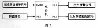
The working process of the remote controller is as follows (Figure 2): the remote controller has a built-in single chip AT89C51. When the interrupt 0 receives the edge trigger signal, it enters the alarm program, and the P1.3 end of the single chip is set to 0 to sound and light alarm. When it is detected that the closing switch is closed, the audible and visual alarm is turned off; the P1.1 of the single-chip microcomputer outputs a pulse signal, and the transmitter emits a frequency signal, which is received by the alarm device in the car (this control is to prevent the audible and visual alarm in the car from false alarm) At the same time, the interrupt 0 of the remote control itself is turned off to prevent false alarms. ?
 ?
? 
2.3 Anti-theft transmitting circuit and receiving circuit (1) Transmitting component CZ-7F: The internal is composed of high-frequency tube MPSH10 for carrier oscillation and transmission, plus an additional input signal transistor 8050 amplifier. The modulation method is frequency modulation, the carrier frequency is 280MHz, the operating voltage is 6 to 12V, and the modulation voltage is 6V. This component has three pins, 1 foot UDD is the positive power terminal, 2 feet are the modulation signal input terminal, and 3 feet USS are the negative power terminal.
(2) Receiving component CZ-7J: composed of detection demodulation circuit and power circuit LM358, etc., paired with CZ-7F. The typical operating voltage is 6V. There are also three pins on the outside: 1 foot UDD is the positive power terminal, 2 feet are the demodulation signal output terminal, and 3 feet USS are the negative power terminal. The pair of remote control components have mature circuits, stable operation and high reliability, and can be used to transmit digital or analog signals. The effective working distance is not less than 600 meters. All components including the antenna have been adjusted.
(3) Anti-theft transmission circuit: When working normally, the P1.4 terminal of AT89C51 is high level, no pulse is emitted, and the transmitter does not work. When an anti-theft signal is detected (that is, the human body), the internal program uses a timer to control the transmission of a 50kHz pulse. After being buffered by the inverter, the transmitter works to transmit the required signal.
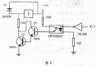
(4) Anti-theft receiving circuit: when the transmitter on the remote controller transmits pulses, the receiver receives the signal, and the output signal after amplification and shaping is received by the interrupt port of the single-chip microcomputer and transferred to the corresponding interrupt program for processing.
3.2 Software function (1) Monitoring function: When the monitoring button is pressed, the single-chip microcomputer makes corresponding processing;
(2) Display function: display distance and alarm information;
(3) Interrupt function;
(4) Data conversion function. Due to space limitations, the main program flow chart is omitted.
Offer Windows 10 Posready,Windows 10 Point Of Sale,Posready Windows 10 From China Manufacturer
Best Window 10 Pos System for retail
If you own a retail store, you likely need a retail Window 10 Pos System that offers inventory management and can connect to a bar code scanner and receipt printer. Our custom retail point of sale for small business, does all this and more.
We also offer easy-to-use email marketing software with effective templates and sample copy to let your customers know about your sales and special promotions.
Best Window 10 Pos System for contractors and home repair
mobile payment processing
Window 10 Pos System
Windows 10 Posready,Windows 10 Point Of Sale,Posready Windows 10,Square Point Of Sale For Windows
Shenzhen Gmaii Technology Limited , https://www.gmaiipos.com