1 Introduction
This article refers to the address: http://
The automobile assembly line is an important part of the entire automobile production line, and its operation status directly affects the quantity and quality of the automobile production. To this end, the project design is based on the step7 plc control system, the project software platform by Siemens wincc6.2 to achieve the car assembly line monitoring system and related alarm system.
Siemens' wincc configuration software has the powerful function of monitoring the production process and is based on the personal computer's data acquisition and monitoring control system. It can monitor and control the running equipment on site, and realize various functions such as data acquisition, equipment operation, parameter adjustment and various signal alarms. Wincc has a wide range of applications and strong compatibility, providing mature and reliable operation and efficient configuration functions, as well as flexible configuration capabilities.
2 system overall design
The monitoring system of the Brilliance Jinbei a1 vehicle assembly shop consists of a central control room and seven plc control stations on site. The entire control system adopts the mode of “centralized monitoring and decentralized controlâ€. According to this principle, the whole system is divided into three levels, namely, monitoring layer, control layer and equipment layer. Different network structures and hardware and software configurations are used in each level to achieve different functions. The system composition is shown in Figure 1.
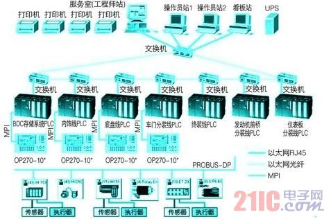
Figure 1 The overall composition of the monitoring system of a1 car assembly shop
2.1 Main functions of the monitoring layer
The central control room uses the computer monitoring system to perform real-time collection and centralized monitoring of the operation information of each controlled device in the workshop (referred to as data that can be transmitted to the computer monitoring system via Ethernet) through Ethernet (ethernet). The central control room is equipped with one data acquisition server (engineering station). As the scada server (monitoring control and data acquisition) system, the windows 2003 server is used as the operating platform, and the operation control software (step 7) completes the production line control software compilation and downloading and faults. Diagnose, run configuration monitoring software (wincc6.2), complete the collection of equipment control information and production data, process processing, generate various files, display dynamic pictures and graphics of each production area, production equipment status of the area , production status, logistics status for dynamic simulation, real-time monitoring, and real-time reflection of the various interfaces and equipment in the production process.
Two monitoring computers (operator station), one kanban system control computer, read the information in the database from the scada server, establish a display interface and monitor the running status of the device in real time, and automatically record process parameters and print fault reports. . The central control room and the plc network use an Ethernet switch to connect the network, and the connection between the Ethernet switches uses optical cables.
2.2 Main functions of the control layer
The control layer uses the plc and profibus field bus to receive the data information sent from the site. After cpu calculation and processing, the corresponding command (output signal) is issued to control the field device. At the same time, the control system of each major single device has the following functions:
(1) It can realize independent control of the equipment itself and meet the process requirements;
(2) Any data that needs to be monitored centrally in the central control room (such as operating conditions, fault information, etc.), the control system of each single device can independently collect in real time;
(3) Must have the network interface (Ethernet) required for the central computer monitoring system.
2.3 Main functions of the device layer
The equipment layer mainly includes field operation stations, field sensors (proximity switches, photoelectric switches, etc.), other input devices on the site (such as control buttons, etc.), display devices (such as indicators, etc.), directly or through the fieldbus and control layer. Plc is associated with sending the input signal to plc and sending the plc output command to the field device.
In the production line, manual or manual control is required. In principle, local operation stations should be set up in the relevant areas of the site and next to the main special planes and single line (body) equipment, such as elevators, transfer machines, turntables, chain conveyors on the production line. Machine and so on.
Because it is the same Siemens product, the seamless and high-reliability communication connection between wincc and s7-300 plc can meet the needs of real-time monitoring and network expansion of the assembly shop.
3 car assembly line plc control program design
The control system of the automobile assembly line is relatively complicated. Therefore, the entire assembly line is divided into 7 lines to be separately controlled, namely: bdc storage line, interior line, door line, chassis line, engine line, instrument line, final final inspection line. . The plc programs of each line can operate independently with interlocking signals between each other.
Using Siemens step7 as a programming tool, in order to meet the needs of the upper computer wincc monitoring system and the design requirements of the reporting system, the relevant dynamic data files are designed while developing the plc control program, which provides corresponding variables for the monitoring and control of the upper computer. And data, also provides relevant raw data for the reporting system [2].
4 wincc monitoring program development
4.1 PC monitoring system function
According to the process flow, process parameters and monitoring requirements of the assembly shop, the PC monitoring system was designed and developed, and the screen was divided into main screen, bdc body storage area, interior assembly line, door line, chassis line, engine front axle assembly line, Dashboard assembly line and final assembly inspection line. The macro operation of the entire workshop can be displayed on the main screen of the monitoring system. You can switch to the monitoring screen of other distribution lines at any time by switching the buttons at the bottom of the screen.
In addition to the operation status display, fault display and setting of storage area and assembly line, it can also control the operation of the interior line, door line, chassis line and final assembly line of storage area and assembly area, including the whole line. Start stop, single line start stop, storage area selection program, manual selection, and speed adjustment.
In addition, the system includes a comprehensive alarm and reporting system that can count, save and print faults on the production line.
The main screen of the monitoring system is shown in Figure 2.
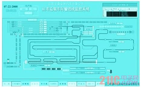
Figure 2 main screen of a1 car assembly shop monitoring system
4.2 Monitoring system screen configuration
The upper computer (engineer station) installs the wincc development version, and the operator station installs the running version. It provides functional templates for graphical displays, messages, archives, and reports for industrial applications, making it easy to generate fully graphical human-machine interfaces. The upper computer is equipped with step7 programming software, and is connected to the on-site plc by Ethernet. It can realize monitoring and modifying the plc program in the central control room.
Before configuring the screen, first establish a dynamic connection between wincc and step7. The communication between wincc and plc mainly depends on the simatic s7 protocol suite protocol channel in the s7 protocol. Establish the connection between the host computer and each branch line plc by setting the Ethernet address, rack number, slot number, and so on.
After the connection is established, wincc monitors the on-site operating status by creating variable tags, drawing configuration screens, variable connection and debugging of component properties.
(1) Create variable tags: After the plc and wincc communication handshake is established, the corresponding tags in the plc program should be created in wincc. It should be noted that the plc variable selected in wincc must correspond to the variable address in the plc program.
(2) Drawing configuration screen: In the wincc graphic editor screen, according to the equipment layout and monitoring requirements of the assembly shop, all the monitoring screens and other operation screens that can reflect the scene status in real time are completed by using the wincc drawing tool or the compatible drawing software. When drawing, try to make the position of the screen and components consistent with the scene, and fully take into account the user's operating habits in the future, and make the screen simple, friendly and easy to operate.
(3) Dynamic connection of components: To dynamically reflect the operating state of the field device, variables such as color, style, flicker, geometry, etc. of the drawn components are connected. When the variable changes, the attribute of the component changes accordingly, so that the working state of the monitored system can be monitored and displayed visually. When debugging, it should be noted that the action time period of drawing the component is consistent with the action time period of the actual component. Figure 3 shows the monitoring screen of the chassis line maintenance lift.
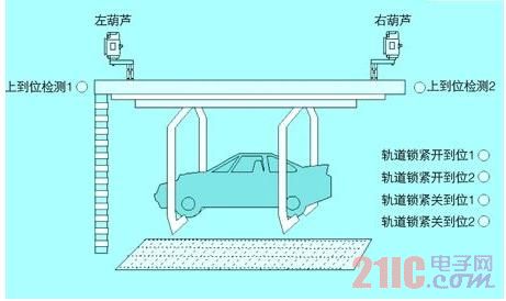
Figure 3 Chassis line maintenance lift monitoring screen
4.3 Alarm System Configuration
In industrial production, safety is undoubtedly the most important, and any measures should be taken to reduce the occurrence of failures. The operator should be notified in time when the fault occurs. Therefore, the alarm message system is of great significance to the normal operation of the whole system. It is an important part of the human-machine interface application system.
(1) Configuring the alarm screen: Using the wincc alarm control alarm control provided by wincc, the trigger condition, display color and description of various alarms can be configured, and real-time and historical data can be displayed and confirmed. The historical record can be set to both short-term and long-term, and it can be refreshed in real time in a first-in, first-out manner. By modifying the relevant settings, the alarm information can be stored, the storage period can be set according to the customer's requirements, and the alarm information can be extracted according to the input time period and printed out by the report form. Therefore, the database is the source of statistics for various data reports. Figure 4 shows the short-term alarm message window.
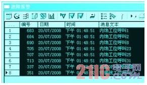
Figure 4 short-term alarm message window
(2) Design and implementation of the reporting system: The wincc reporting system is more powerful and provides optional functions for user archives. Its role is to save the data in wincc in the built-in wincc database with a user-defined structure. This data can be displayed by the active x control in a tabular manner. Therefore, various report table structures have been designed according to actual needs. The reporting system can be used to count the start time, downtime, and fault time of the production line, and save and print the time, location, cause, and downtime of the equipment failure.
5 Conclusion
The system is simple in operation, easy to modify the process parameters, and after commissioning and running in the Brilliance Jinbei a1 car assembly shop, it has been in operation since 2008 and has not been operated until now. Therefore, from the field use situation, the hmi interface with wincc as the PC configuration software is friendly and functional, which not only fully meets the process requirements of the plant, but also improves the automation control level and production efficiency.
Home Window C leaning Robot
Home Window Cleaning Robot is usually used for cleaning ash, water stains, oil stain on both side of window. Home Window Robot need to connect power to use through by remote control. Window Robot Home Cleaning can reduces the difficulty and danger of window cleaning in tall buildings but more efficient with Two models (dry cleaning and wet cleaning). Window Cleaning Robot Amazon sale very popular,welcome to place order.
Outdoor Window Cleaning Robot help us clean outside window glass,its dangerous, Window Cleaner Robot For Sale ,welcome to send us enquiry.
Advantage of Robot Window Cleaner :
Window robot cleaning with three types for cleaning route.
Glass robot has folding handle to achieve slim body.
Voice broadcast to remind you.
Super suction is more suitable for Building Window Cleaning Robot.


FAQ:
1.Can I place an order online?
Yes,please order from our online store aliexpress or amazon
2.How can I get some samples promptly?
Yes,we have stock
3.How about the payment terms?
T/T
Home Window Cleaning Robot
Home Window Cleaning Robot,Window Galss Cleaning Robot,Home Window Robot,Window Robot Home Cleaning, Window Cleaning Robot Amazon,Outdoor Window Cleaning Robot
Zhengzhou Bangmi Smart Technology Co., Ltd. , https://www.globalcleanrobot.com