Overview
With the continuous rise in domestic labor costs and the gradual disappearance of the advantage of low-cost labor in China, "machine substitution" has become an inevitable trend. Meanwhile, China's manufacturing sector is transitioning towards higher-end industries, taking on advanced international manufacturing tasks, and placing increasing demands on the development of industrial robots in the direction of intelligence. Intelligent industrial robots will undoubtedly become the future technological high ground and economic growth point.
Intelligent industrial robots integrate personal software modules, sensors, and vision systems in the best possible way. Among the intelligent elements of the robot, the vision system plays a core role, particularly in high-precision scenarios where, without the guidance of the visual system, the robot cannot complete its tasks. For robot vision guidance, the MicroMatch Smart Camera is an excellent choice.
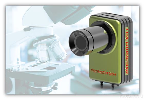
The MicroMatch Smart Camera is an ultra-compact, integrated smart camera developed by McMasch Electronics. It enables rapid and precise inspections across all parts and components in every industry. Its compact size facilitates easy installation on space-constrained production lines, and its unique modular design allows for on-site customization according to specific application requirements.
The MicroMatch smart camera offers a cost-effective solution. The Micro6000 series of industrial smart cameras come with a small, rugged, industrial-grade housing that is resistant to vibration and shock. They also integrate RS-232/485, Ethernet, and multiplex digital I/O, VGA output display, USB peripheral input, and other hardware interfaces, enabling communication access with different brands of equipment on various industrial sites. The Micro6000 series smart cameras are widely used in automated manufacturing of electronics products and consumer goods, including food and beverage, pharmaceuticals, packaging, logistics, aviation, semiconductors, solar energy, new energy batteries, and robot positioning and guidance industries.
Key Technologies
There are numerous key technologies involved in robot-guided vision applications, primarily focusing on vision-related aspects.
Firstly, coordinate calibration technology (hand-eye calibration):
In robot guidance applications, conversions between multiple coordinate systems—robot coordinate system, tool coordinate system, image coordinate system—are involved.
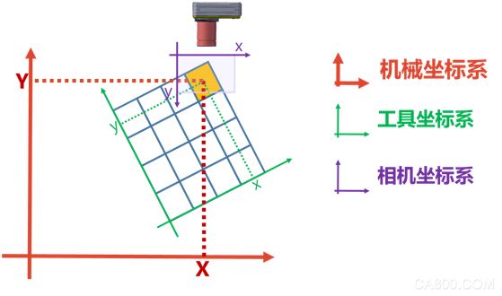
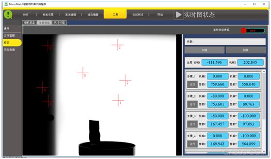
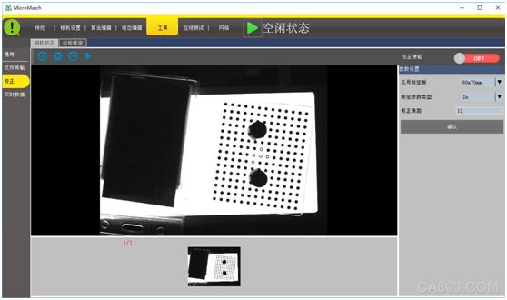
In such applications, the correspondence between the various coordinate systems must first be determined. The MicroMatch Smart Camera provides an automated method for performing calibrations between various coordinate systems.
The automatic calibration method for many visual products involves fixing or installing the calibration plate on the robot. However, this method has significant limitations in practical projects. In many cases, especially in high-precision situations, the camera’s shooting position may be outside the robot's stroke, or due to mechanical structural design, the robot cannot move to the camera’s field of view at all.
To address these issues, MicroMatch employs a more flexible calibration scheme that allows the robot to pick up a "rigid body" with obvious features. As long as the "rigid body" section enters the camera’s shooting range and completes a series of specified actions, calibration can be completed quickly and conveniently.
Since the robot grabs an "arbitrary rigid body" without preset feature points, the advanced algorithm configuration function of the MicroMatch software is required to extract the feature points.
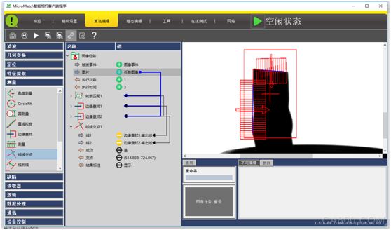
After the algorithm extracts the feature points, it automatically determines the position of the feature points after movement according to the specified movement and completes the calibration.
Secondly, lens distortion correction technology:
Lens distortion is an inherent perspective distortion of the optical lens, which is an inherent characteristic of the lens and cannot be eliminated but can only be improved. This kind of distortion is very detrimental to the visual image quality of the photo. Lens distortion causes the position of the actual image feature points to deviate. In high-precision visual guidance projects, the distortion of the lens must be accurately corrected.
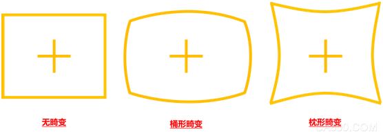
Although the lens distortion correction technology is relatively mature, it is more complex in actual project applications. A very prominent problem is that due to limitations of the installation space of the mechanism, light source illumination mode, etc., a complete calibration board image cannot be obtained, which poses a significant challenge to the calibration work.
To solve this problem, the MicroMatch smart camera adopts a customized calibration plate and a more robust calibration algorithm. It can accurately complete the lens distortion calibration when the calibration plate is incomplete, partially obstructed, or even partially blocked inside the calibration plate.
Fix the distortion calibration when part of the calibration plate is occluded
Thirdly, robot rotation compensation technology:
In actual robot guidance projects, robots need to customize different "fixtures" according to the captured products, which brings a very big problem to high-precision robot guidance projects, specifically the deviation between the center of the fixture and the rotation center of the robot. This deviation directly leads to a significant decrease in accuracy in many items involving rotation, and correcting this deviation is very complicated.
Some foreign robot control systems support rotation center compensation technology, but this compensation can only be achieved through visual inspection. The "visual" correction method will seriously reduce system accuracy and can only mitigate the impact of this factor to some extent, but there is no guarantee of accuracy. Moreover, most domestically produced robot systems do not have this function. Compensation for the robot's rotation can only be solved with a matching vision system.
Fourthly, multi-logical multi-objective management technology:
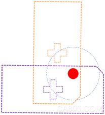
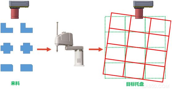
In many robot-guided projects, the robot needs to involve multiple logical and multi-objective controls. A robot needs to grab a different product and then place it in a different target location, as illustrated in the figure below.
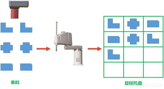
Because the target tray has multiple points, it needs to be placed in order according to the type of product and the desired target position. The management of the target position is more complicated. This part of the work can be managed by the robot, but maintaining and modifying the robot program is cumbersome. Furthermore, the position of the target tray is not fixed, as shown below.
For this requirement, the usual control logic is:
The left camera sends the product coordinates and model number to the robot. The right camera sends the position change of the target tray to the robot. The robot calculates the position of the tray (red grid) after the change according to the preset target grid and pallet position changes. Place it in a different location depending on the product model.
This method has two problems in actual operation: 1. Many robots do not support the function of calculating the coordinate transformation according to the deviation (translation and rotation) (calculating the position of the red grid according to the green grid and the deviation); 2. The product placement accuracy is relative to the tray, and the position of the target tray in the robot coordinate system cannot be accurately determined.
For this complex scenario, the MicroMatch Smart Camera System integrates multiple logical and multi-object management functions into the software. It does not require the robot module to read the product type, nor does it require the robot to calculate the position change of the tray based on the variation. Instead, the final target position that the corresponding product needs to be placed is directly sent to the robot at one time, which greatly reduces the coordination complexity between the vision and the robot.
Fifthly, communication technology:
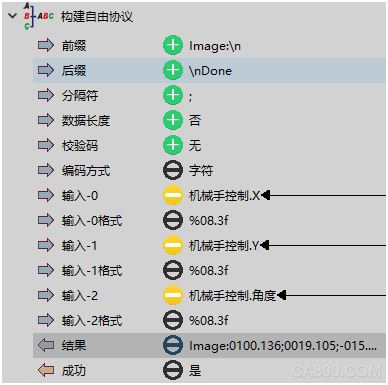
As a standard product, the MicroMatch Smart Camera is perfectly suited to facilitate the application of various robot vision guidance projects and to communicate with various brands of robots. The MicroMatch smart camera adopts unique and convenient "free protocol" technology, which can complete the docking work with various robots without programming based on the communication rules of different robot manufacturers.
If the manipulator requests to send 3 data (X, Y, and angles), each data having 8 significant digits, and reserving 3 decimal places after the decimal point, with each digit separated by a number, the required protocol format is:
Image:
0000.000;0000.000;0000.000
Done
Use the MicroMatch Smart Camera's Build Free Protocol Module to set the following parameters:
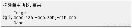
The corresponding output is:
Typical Cases
First, the metal assembly case:
The project requirement is that the manipulator blindly catches the "metal piece" and then takes a photo at the top of the camera. The MicroMatch intelligent camera takes a photo and controls the manipulator to place the metal part at the specified position. The project needs to assemble five different "metal parts." Two robots and two MicroMatch smart cameras are used to speed up the process. Two are assembled on one table, and three on another. Since the five pieces of the captured product are different, the corresponding placement positions are also different. Since the MicroMatch smart camera has multiple logical processing functions, a simple smart camera can control the robot to grab the "different" products and place them at "different" target positions.
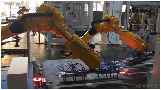
(Plan Implementation Site)
1. Perform lens distortion correction and hand-eye calibration using automated methods;
2. Use the algorithm configuration function of MicroMatch software to extract the product feature point coordinates;
Due to the design of multiple logical controls, the configuration algorithm reads the robot instructions and then makes logical decisions, executing different algorithms based on the instructions.
3. Calculate the product rotation angle;
4. Robot rotation compensation;
5. Build a robot communication protocol;
6. Serial output control robot movements;
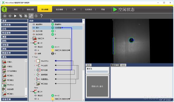
(Algorithm Flowchart)
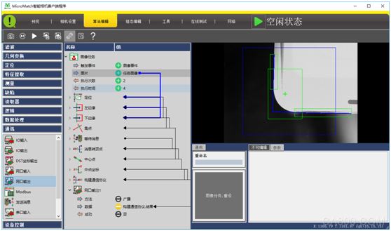
In addition to supporting any editing algorithm flow, the MicroMatch smart camera system can also customize the publishing interface. The delivered project interface is as follows:
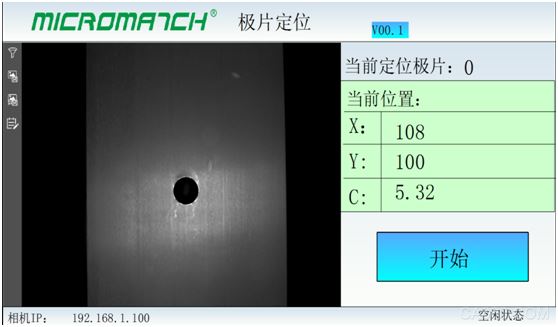
(Configuration Interface)
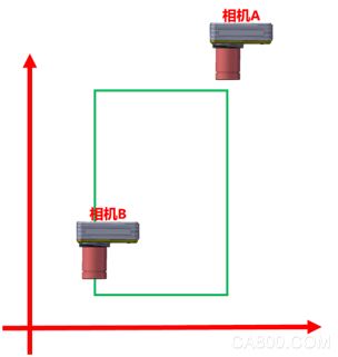
Secondly, high-precision fitting case:
The background of the project is the high-precision fit of the screen, with the robot's pasting precision at 6u, and the scheme adopts dual cameras to shoot diagonally to improve accuracy. Due to the need for dual camera cooperation, one camera's data needs to be sent to another camera, and the other camera receives the data and calculates the final result to control the robot.
1. Camera A control program:
Camera A gets two sides of the phone, then calculates the intersection of the two sides, then uses the Send Message module to send the point to Camera B
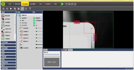
2. Camera B control program:
Camera B uses the same method to acquire another intersection of the screen, then uses the "receive message" module to receive the coordinates from camera A, calculates the center coordinates, and uses the robot module to perform the rotation compensation. The compensated value controls the robot movement.
In summary:
The MicroMatch smart camera greatly lowers the threshold for manipulator vision guidance control. It can not only achieve single-camera cooperation but also can achieve multi-camera coordination in high-precision multi-station complex application scenarios, integrating software, multi-logical and multi-object management, and reducing robotic programming workload.
hybrid fiber optic cable,hybrid fiber cable,hybrid cable fiber,hybrid fiber optic
Guangzhou Jiqian Fiber Optic Cable Co.,ltd , https://www.jqopticcable.com