The **74HC04** is a high-speed CMOS inverter IC designed for use in digital logic circuits. It is compatible with low-power Schottky TTL (LSTTL) and operates using a silicon-gate CMOS technology, making it ideal for applications where speed and power efficiency are important.
The 74HC04 consists of six independent inverter gates. Each inverter has a single input and a single output, meaning that when the input is at a high level, the output will be low, and vice versa. This makes it a versatile component for signal inversion, buffer applications, and logic design.
### Pin Configuration and Internal Structure
The device is typically housed in a 14-pin DIP package. The pinout includes six pairs of input-output pins (1A to 6A, and 1Y to 6Y), along with two power supply pins: VCC (positive supply) and GND (ground). The internal structure of the 74HC04 comprises six CMOS inverters connected in parallel, each operating independently.

### Logic Function and Truth Table
The logic function of the 74HC04 is straightforward—each inverter simply inverts the input signal. The truth table illustrates this clearly:
| Input (A) | Output (Y) |
|-----------|------------|
| 0 | 1 |
| 1 | 0 |
This behavior is consistent across all six inverters within the IC.


### Electrical Characteristics
The 74HC04 is known for its wide operating voltage range and low power consumption. Here are some key electrical characteristics:
#### Recommended Operating Conditions
| Parameter | Min | Typ | Max |
|---------------------|-----|-----|-----|
| Supply Voltage (VCC) | 2 | 5 | 6 |
| Operating Temperature | -40 | 25 | 85 |

#### DC Electrical Characteristics
| Parameter | Min | Typ | Max |
|-----------------------|-----|-----|-----|
| Input High Voltage | 2.0 | 3.5 | 6.0 |
| Input Low Voltage | 0.0 | 0.8 | 2.0 |
| Output High Voltage | 4.5 | 5.0 | 5.5 |
| Output Low Voltage | 0.0 | 0.2 | 0.4 |
| Input Current (VIH) | -10 | 0 | 10 |
| Input Current (VIL) | -10 | 0 | 10 |

### Applications
Due to its simplicity and reliability, the 74HC04 is widely used in digital circuits for tasks such as signal inversion, buffering, and logic level shifting. It is also commonly used in clock generation, pulse shaping, and interfacing between different logic families.
In summary, the 74HC04 is a fundamental building block in digital electronics, offering high performance, low power, and easy integration into a variety of circuits. Whether you're designing a simple logic circuit or a complex digital system, the 74HC04 is a reliable choice.
Mechanical Timer Socket
24 hours mechanical timer
Instant indicator
Min.setting time:15 minutes. Max.setting timer:24 hours
With hand switch,can be switched to operating and
setting at any time
Instructions:

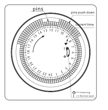
1. Set program: 1 pin is equivalent to 15 minutes. Determine desired start time and push down pins until desired
off time.
For instance, if you want electrical devices to work from 8:00am to 11:00am and from 13:00pm to 17:00pm, you
just need to put down allthe pins between the three period time.
2. Set the current time: Turning the dial clockwise until the arrow pointing to
current time.
For example,if now it is 8:00 am, please turn the dial and make sure the
arrow point to 8. (See the picture.)
3. Plug the electrical device directly into the timer. Make sure the electrical
device is power-on.
4. Plug the timer into electrical outlet and the electrical device will be work
according to the setting program.
Note: = Normal Ope n = Timing
Make sure the switch on the Timing position. If it
is on the [Normal Open" mode, the electrical device is
always power-on and the timer function no work.
Specifications:
Rated Voltage, Current and Power
|
As shown on the label
|
Time Setting Range
|
15minutes24hours
|
Working Temperature
|
-10℃?+55℃
|
Operation
|
Clockwise
|
Insulation Resistance
|
>100M
|
Inherent Loss
|
≤1W
|
Application:
1. To enable high-power electric appliances to run automatically at off-peak time if there is different electricity
price according to different periods of time in some areas.
2. To use for electric appliances which need time control, such as water heaters, air conditioners, drinking
fountains, rice cookers, advertising lights and so on.
3. To control the charging time. For example, battery of electric bikes or mobile phones, storage batteries, etc.
4. Occasions which need switch on/off frequently, like interval spray irrigation for flowersand lawn, cyclical
adding oxygen to fish jar, fountains and so on.
5. Home safety precautions and lighting.
Caution:
1.D o not exceed the maximum ratings of the timer.
2.M ust reset the current time after power failure.
3.D o not plug the timer directly into the working electrical appliances.
4.U nless changing the setting, keep the program same every day.
5.D o not disassemble timer by yourself. Professionals service are needed for maintenance.
6.T his item is only for indoor use.
Plug-in Mechanical Timer, Mechanical Timer Socket, 24hr Mechanical Timer, Mechanical Timer Plug, Mechanical Timer Adaptor, Mechanical Electric Timer Switch
NINGBO COWELL ELECTRONICS & TECHNOLOGY CO., LTD , https://www.cowellsockets.com
