This project focuses on developing a portable radio frequency identification (RFID) reading and writing system. The AT90 series microcontroller unit (MCU), known for its enhanced RISC architecture and built-in Flash memory, serves as the central control device. Data is stored in an RF IC card, which communicates with the reader through non-contact data transmission. The system outlines the corresponding circuit design and program flow. Due to its strong anti-interference capability and high reliability, RFID systems have seen rapid development in recent years and are now widely applied across various industries.
In recent years, automatic identification technologies have gained widespread adoption in service sectors, logistics, commerce, manufacturing, and material distribution. These systems aim to provide information about people, animals, and goods, improving efficiency and accuracy in data management.
Currently, most RF cards operate at 125 kHz, but this frequency requires large Coils—often hundreds of turns—which makes it difficult to integrate into small plastic cards. This limits their use in compact applications. To address this issue, this system uses a transponder operating at 13.56 MHz. Its coil consists of only about five turns, significantly reducing size and making it more portable. This opens up new market opportunities, such as using non-contact IC cards (RF cards) for public transportation tickets, access control, attendance tracking, and even highway tolls, gas stations, and parking lots.
Additionally, the system can be adapted for use in blind navigation systems. By installing the reader in a walking stick and using a coin-sized RF card, users can receive real-time guidance when approaching important buildings or intersections. Although GPS-based navigation systems exist, they are often expensive and prone to errors, limiting their widespread use. In contrast, this system utilizes the cost-effective AT90S8515 microcontroller, offering better performance, practicality, and scalability for future applications.
The communication protocol of this system is serial, asynchronous, and full-duplex. It follows the international standard ISO14443, which defines the working principles and parameters of 13.56 MHz RFID cards. The standard is divided into four parts: physical characteristics, RF interface, initialization and anti-collision, and data transmission protocol.
According to ISO14443, the RFID system operates at a baud rate of 106 Kb/s, with a carrier frequency of 13.56 MHz. Data transmitted from the reader to the RF card is modulated using 10% amplitude shift keying (ASK), asynchronous timing, and non-return-to-zero (NRZ) encoding. A subcarrier at 847 kHz is used for data sent from the RF card to the reader, employing phase shift keying (PSK) and NRZ encoding.
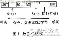
The RF card model used in this system is the AT88PF256-13, which fully complies with the ISO14443 standard. It specifies a particular data packet format, as illustrated in Figure 1.

In the frame format from the reader to the RF card, there is no protection bit (EGT). However, the RF card's response includes an EGT for error detection and improved reliability.
The main control unit in this system is the advanced AT90S8515 microcontroller from the AVR series. It handles keyboard input, display output, controls modulation and demodulation units, and couples signals to the transponder (PICC) via the antenna to perform reading and writing operations. Additionally, it supports online programming and debugging through the serial download port.
Key features of the AT90S8515 include:
- 8 KB of Flash program memory
- 512 bytes of EEPROM
- 512 bytes of SRAM
- 32 general-purpose I/O ports (4x8 bits)
- 32 working registers
- One 8-bit prescaler timer
- One 16-bit timer with counter, capture, and PWM functions
- Two external interrupt sources
- On-chip analog comparator
- Programmable UART
- Programmable watchdog timer
- SPI port and two software-selectable power-saving modes
3.1 Input and Output Unit
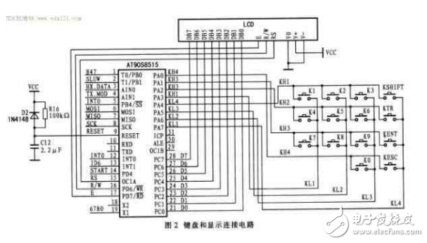
The system includes a 4x4 external keypad, featuring special function keys such as SHIFT, KTR, KENT, and KESC, to handle input commands. A standard LCD is connected for output display. The main controller processes user inputs, converts them into the frame format defined by ISO14443, and sends them via the modulation and coupling (antenna) unit. When the transponder responds within its range, the data is received through the coupling and demodulation units, processed, and displayed on the LCD. The connection diagram of the input and output section is shown in Figure 2.

Coils
Car Phone Wireless Charging Coil,Circuit Board Induction Coils,Intersection Induction Coils,Induction Coil Set
Shenzhen Sichuangge Magneto-electric Co. , Ltd , https://www.scginductor.com