This is a 1000W pure sine wave inverter boasting up to 94% efficiency and comprehensive protection features.
Figure 1:
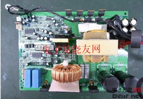
Figure 2:
Image 3:
Figure 4:
Figure 5:
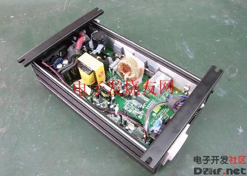
Figure 6:

Figure 7:
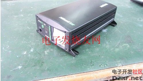
Figure 8:

Figures 9 and 10 demonstrate the inverter's performance under a 1200W load using a WT230 power meter to measure voltage, current, and power. An oscilloscope monitors the inverter’s output waveform. This inverter has a robust load-carrying capability, capable of starting 1/2HP motors, chainsaws, refrigerators, TVs, induction cookers, and microwaves. It features voltage, current, and power monitoring displays, along with protection mechanisms such as high-voltage alarms, high-voltage protection, low-voltage alarms, low-voltage protection, over-temperature alarms, over-temperature protection, output over-voltage protection, overload protection, short-circuit protection, and remote control functionality.
Figure 11:
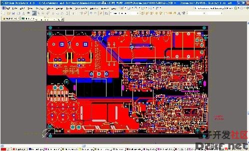
Figure 11 illustrates the PCB layout of a 1000W pure sine wave inverter.
Figure 12:
The schematic in Figure 11 includes an auxiliary power supply, a DC-DC boost control section, and a microprocessor for monitoring DC input voltage, current, and power.
Figure 13:

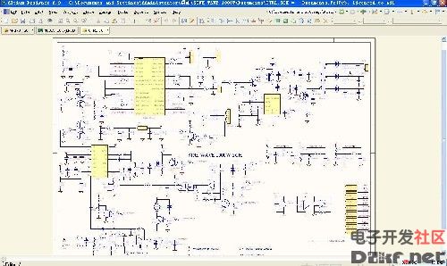
The schematic in Figure 13 comprises a DC-DC power section, a DC-AC power section, a DC-AC control section, and an output protection circuit. The DC-AC control generates a pure sine wave primarily through Microchip’s 16-bit DSP DSPIC30F2010 SPWM via the DC-AC power section. For details on the algorithm used to generate SPWM, refer to the DSP programming section.
Figure 14:
Figure 15:
Figures 14 and 15 showcase the DSP DSPIC30F2010 program design. The algorithm for generating SPWM is briefly explained below. A constant list is created based on the alternating current expression Umsin ωt, where Um represents the amplitude of the alternating current and also the DC boost. The software derives the SPWM, whose duty cycle changes according to the sinusoidal function, by referencing the table, converting it into a pure sine wave voltage through the DC-AC power section. When Um remains constant, a stable AC voltage is produced. However, the actual DC boost is not entirely stable. Thus, it is essential to multiply the AC expression Umsinωt by a coefficient C as compensation to achieve a pure and stable sinusoidal AC voltage. The compensated AC expression becomes UmCsinωt, where C = Um/U. Um represents the output sinusoidal AC voltage amplitude, and U is the current DC boost. Stable sinusoidal AC voltage is obtained when U ≧ Um.
Here’s an example of compensation:
Assume the current DC boost U is 360V, the output voltage is 220V AC, and the AC power amplitude Um is 311.08V. Then, C = 311.08/360 = 0.864. At this point, the software retrieves the current SPWM duty cycle by referencing the constant in Umsinωt and multiplying it by 0.864.
2U 4U Atx Power Supply,Atx 1800W Server Power Supply,Atx 1800W Power Supply,Active Pfc Power Supply For Computer
Boluo Xurong Electronics Co., Ltd. , https://www.greenleaf-pc.com