AMBE is a low bit rate, high quality voice compression algorithm based on MBE technology. It has the advantages of good voice quality and low encoding baud rate, and is embedded in the AMBE-1000 voice compression chip of DVSI. The chip is a high-performance multi-rate speech encoding / decoding chip, and its speech encoding / decoding rate can be varied from 2400 to 9600 b / s at intervals of 50 b. There are independent voice encoding and decoding channels inside the chip, which can simultaneously complete the voice encoding and decoding tasks; and all the encoding and decoding operations are completed inside the chip, without the need for external memory expansion. These characteristics of AMBE-1000 make it very suitable for digital voice communication, encrypted voice communication and other occasions that require digital processing of voice.
2 Working principle and hardware interface of AMBE-1000
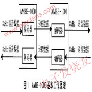
2.1 Basic workflow
Simply put, the working process of AMBE-1000 is shown in Figure 1. AMBE-1000 can be seen as composed of two separate encoders and decoders. The encoder receives a sample stream of 8 kHz voice data (such as 16-bit linear, 8-bit A-law or 8-bit U-law) and outputs a desired baud rate channel data stream. Conversely, the decoder receives a channel data stream and synthesizes a voice data stream. The interface timing of the encoder and decoder of AMBE-1000 is completely asynchronous.
2.2 Channel interface
The channel interface is used to describe the compressed bit stream output from the encoder and the compressed bit stream input to the decoder. The interface can also output status information, for example, can detect whether there is dual tone multi-frequency (DTMF) voice signal input. In addition, the interface performs more complex control operations on the codec / decoder (usually during initialization). These control functions include voice and error correction code speed selection, and A / DD / A chip devices. In most voice transmission systems, the actual encoded bit stream is extracted from the channel in a certain format, and combined with the system information to form the system transmission data stream, which is sent through the transmission channel; it is extracted at the receiving end and passed through the decoder It constitutes the data stream in the format required by AMBE-1000.
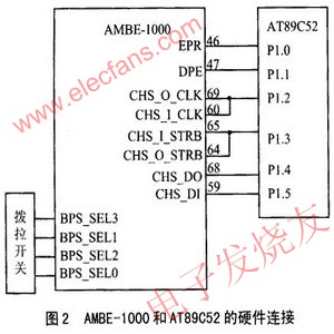
AMBE-1000 has multiple working modes: parallel and serial, framed and unframed formats, active and passive. Among them, the parallel passive frame mode is the most flexible and practical working mode. By connecting the pull-up resistor and the dip switch to the corresponding interface selection pin, the corresponding working mode can be selected. By adopting the above method, the speech rate and error correction code rate can be freely selected between 2400-9600b / s and 50-4750b / s through the selection switch. In serial active mode, the working clock of AMBE-1000 is 27MHz, and the clock of CHS_O_CLK is 4.5MHz (27MHz / 6), that is, one bit of data needs to be read within 0.22μs. Even if the single-chip microcomputer works at 24MHz, the data cannot be read, so the passive mode must be adopted, so that you can set the clock of CHS_O_CLK yourself, but the clock also needs to be able to read 34 bytes of data in 20ms (that is, 1 frame Data); At the same time, the parallel port occupies more interface resources, so the serial passive frame mode is adopted, and its hardware connection is shown in Figure 2.
2.3 Data format
The data of AMBE-1000 is composed of 17 words in a frame format. The encoder outputs 17 words every 20 ms, while the decoder receives 17 words. The first 5 words of each frame are composed of frame header (Header), identification flag (ID), status (output) or control (input) information, and the remaining 12 words constitute the encoding / decoding data. The total of 192 bits of these 12 words is the maximum data rate of AMBE-1000 working at 9600b / s (192b / frame × 50frame / s = 9600b / s). When the data rate of encoding / decoding is lower than 9600 b / s, the insufficient bits are filled with 0s. It should be noted that regardless of the AMBE-1000 operating rate, all 272-bit (17 words × 16b = 272b) frame data (including any unused trailing zeros) must be output from the encoder or input to the decoder. The frameless format can only be used in serial mode.
2.4 Interface circuit between AMBE-1000 and TLC32044
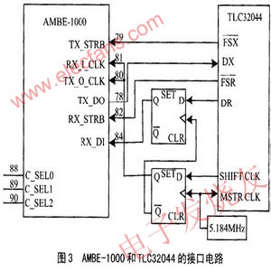
AMBE-1000 requires A / D, D / A voice data and serial input and output. The key of this interface circuit is frame synchronization of voice data, and its hardware interface circuit is shown in Figure 3. Among them, 5.184MHz is used as the working clock of TLC32044, and also used as the trigger pulse of D flip-flop. The shift pulse (SHIFT CLK) generated by TLC32044 is used to realize the synchronous transmission of bits. Select TLC32044 chip by setting C_SEL0-2 to 010.
2.5 Clock and reset
The working clock of AMBE-1000 is 26 ~ 30MHz. It has 3 input methods: TTL clock source direct input, CMOS clock source or oscillator direct input, and crystal oscillator circuit input. In this system, the clock uses crystal oscillator circuit input. The effective reset signal is low and must last for more than 6 clock cycles.
3 Peripheral interface circuit
3.1 Working principle of TLC32044
The digital processing of voice signals is indispensable for A / D and D / A conversion of voice signals. In this design, a 14-bit dynamically adjustable high-precision programmable A / D, D / A TLC32044 chip produced by the American company TI was selected. As shown in Figure 4, TLC32044 consists of anti-aliasing input filters, A / D, D / A, output reconstruction filters, etc. The separation of analog and digital ground, analog and digital power supply can reduce noise and ensure a wide dynamic range. The analog circuit part uses a differential circuit to minimize noise. TLC32044 also has a programmable sampling frequency. The sampling frequency can be controlled by software in the range of 7.2kHz to 19.2kHz. It can work in 4 working states such as synchronous word, byte transmission, asynchronous word and byte transmission. The word or 8bit byte serial communication mode has the highest conversion accuracy of 14bit, and only needs to provide a 5.184MHz clock to work. The chip can accommodate 2 analog signal inputs at the same time through programming. After the system is powered on (or reset), it will work according to its default working mode, that is, according to the 16bit word or 8bit byte serial communication mode, it has a conversion accuracy of up to 14bit, and only needs to provide a 5.184MHz clock to work. The chip can accommodate 2 analog signal inputs at the same time through programming. After the system is powered on (or reset), it works according to its default working mode, that is, synchronous serial communication according to 16bit words, and the sampling frequency is 8kHz. If you want to change the working status of TLC32044, you can program and send the control word to TLC32044 via DX pin.

The D1 and D0 bits in the DR sequence are empty, and the effective accuracy of the A / D conversion is D15 to D2; and the D1 and D0 bits in the DX sequence are used as control bits. FSR and FSX are 8kHz for receiving and sending frame synchronization signals, respectively. In the synchronous working mode, the two are identical.
3.2 Peripheral interface circuit of TLC32044
In order to achieve the system's voice input and output, and at the same time to ensure effective gain, the input and output voice signal must be amplified, the circuit is shown in Figure 5. In this system, a high-performance and low-noise LM1458 amplifier is used, and the gain of the input and output voice signals is adjusted by a 20kΩ adjustable potentiometer. In this circuit, -5V power is required, and the general circuit only provides + 5V power, so the MAX660 chip is used in the circuit design to realize the conversion of + 5V ~ -5V power. In this way, the entire circuit can be powered by a single power supply.

System analysis
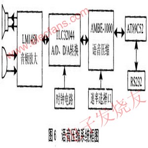
The block diagram of the voice compression system is shown in Figure 6. The system can independently select the working rate. In serial active framed mode. The serial input and output pins of AMBE-1000 can be short-circuited with each other to perform system self-check to confirm whether the system is normal. In the system design, attention must be paid to the distinction between analog ground and digital ground to avoid the introduction of background noise. This circuit design has been applied to the terminal voice compression of intelligent communication terminals, which can reduce the amount of voice data and increase the confidentiality of voice. The circuit can also be used for solid-state interviewers, as long as a flash chip and control keys are added.
APPDU intelligent power management project.Security is a set of professional intelligent power Management System, which can meet the requirements of UPS power supply, AC / DC power supply and Poe power supply, and can realize environmental monitoring and control (temperature, humidity, humidity, humidity) in the computer room. The fire alarm system can realize local and remote operation through centralized control software of power supply, monitor and control power consumption in real time .It can realize the function of building energy management . and develop software interface to any back-end cloud platform at the same time. In the real sense, the intelligent management of interconnection and interworking of power supply equipment in computer room has been realized.
Features:
High efficiency
Energy saving
safety
environment protection
Application:
It Widely used in banks, offices, buildings, office buildings, garden communities, squares, factories, prisons, road traffic, gas stations, ships and other machine room heavy, power failure self-lock, can be embedded in the back-end security system
Intelligent Management System(APPDU)
Intelligent Management System,Management System,Intelligent Blood Collection,Intelligent Management Fiber Optical
Guangdong Steady Technology Co.LTD , https://www.steadysmps.com