Introduction The wireless Ad hoc network is a multi-hop wireless network composed of a group of nodes that can move freely, also known as self-organizing network and multi-hop network. Interference is caused by the signal effects of multiple simultaneous transmission nodes in the same space. Because the data in the wireless ad hoc network is transmitted by radio, if there are other useless radio signals around the link being transmitted, it will cause interference on this link, and the lighter interference will cause the bit error rate to increase. Some data packets are lost; heavier interference will cause transmission failure and link disconnection. The nodes that cause interference are around the receiving node. The root cause of the existence is that the sending node cannot effectively perceive these interfering nodes before sending data. The transmission power of each node in a wireless Ad hoc network cannot be increased indefinitely, and the communication distance of each node is also different according to its own power. Therefore, each node has a communication radius and an interference radius. Among the two radii, the communication radius ensures that the node can receive the signal within this range. If the interference value is controlled within a certain range, the signal can be correctly received; the interference radius (din) represents the area where the node is interfered with, which The size of an interference area is also related to the transmission power of surrounding nodes.
Designing a reasonable carrier monitoring mechanism is one of the effective ways to reduce interference. Among them, the carrier monitoring mechanism based on IEEE 802.11 protocol has been the most widely used. The carrier monitoring mechanism stipulates: before sending data, the node first detects the signal strength of the surrounding channels. If the detected signal strength is greater than the sensing threshold (CSth), it indicates that the channel is busy at this time and the node enters the back-off process; if it detects When the received signal strength is less than the perceptual threshold, data is sent. Therefore, by properly setting the sensing threshold in the carrier monitoring mechanism, the sending node can perceive the interference of the surrounding nodes to the receiving node before transmitting data, so as to determine whether to send the data. In the carrier sensing mechanism, the sensing threshold (CSth) of each node corresponds to a sensing range (Carrier Sense Area). If the nodes in the network use the same transmission power, the sensing range can be formalized as a circle. The radius of this circle is called the sensing radius (din), and the sensing radius is inversely proportional to the sensing threshold.
Compared with the carrier monitoring mechanism, the RTS-CTS mechanism implements channel presetting and occupancy through the RTS-CTS-DATA-ACK four-way handshake and network allocation vector (NAV) settings. However, because the RTS-CTS mechanism has a limited transmission range of the control packet, the receiving node cannot send the CTS packet to all surrounding interfering nodes; at the same time, the RTS / CTS control packet transmission range is fixed and cannot be performed according to the interference range and the actual situation of the link Send distance adjustment. Therefore, the RTS-CTS mechanism has limited ability to control the interference existing around the receiving node. However, through the design of the carrier-sensing mechanism, an appropriate sensing threshold can be selected according to the link status, and an appropriate sensing radius can be determined so that the sending node perceives all interfering nodes, thereby minimizing the interference existing in the link.
This paper proposes a carrier sensing mechanism that minimizes link interference. The receiving node first calculates its interference range according to the link status; and then feeds back the calculated value to the sending node, so that the sending node accurately adjusts its sensing threshold so that it can perceive all interfering nodes around the link, thereby minimizing link interference .
1 Interference model The content of this section describes the interference range of the receiving node and calculates the interference radius, and then considers the accumulation of interference signals to further obtain the corrected interference radius. The interference model proposed in this section is more accurate than the traditional interference model.
1. 1 Interference radius calculation

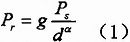
As shown in FIG. 1, the signal strength Pr received by the receiving node r decreases as the distance d between the sending node s and the receiving node r increases, and increases as the distance d decreases. Ps is defined as the transmission power of the transmitting node s, g is the antenna gain, and a is the Path Loss Exponent, which is usually an integer between 2 and 4. Therefore, the signal strength of the receiving node s received at the receiving node r is:
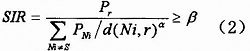
When the sending node s sends data to the receiving node r, another node Ni that is outside the sensing range of the sending node s also tries to send data. The node s does not perceive the existence of the node Ni, which causes interference. In this way, the signals sent by the two nodes s and Ni are superimposed at the receiving node r. Whether the signal of s can be successfully received by r depends on the Capture Effect. For the capture effect, if the signal generated by s at the receiving node is stronger than the signal generated by Ni, then r will successfully receive the data from s, and the weak signal generated by Ni will be ignored as noise. In this paper, the signal-to-noise ratio (SIR) model is used to describe the capture effect: if the ratio of the signal strength received by the receiving node to the interference signal is greater than a certain threshold β, the receiving node can successfully receive the signal:
According to the signal-to-noise ratio model, this article defines the set INr of the interference area node of the receiving node r (INr can also represent the interference area of ​​the receiving node r) as:
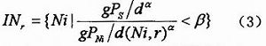
Therefore, the radius din of the interference area is the maximum value of din (Ni, r) in the interference area. According to equation (3), at the same time, we set the transmission power of all nodes in the network to be the same, with PNi = Ps, we get:
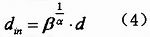
It can be seen from equation (4) that the interference radius of the receiving node is mainly related to the threshold of the signal-to-noise ratio and the distance between the transmitting node and the receiving node.
With our expertise in domain, we offer comprehensive range of Monocrystalline Solar Panels. Our products are used amongst the customers across the country for their effectiveness. We offer products to our patrons as per their needs and are easy to install. These products work using solar energy and have high performance.which are made using high quality raw material and advanced technologies. These Polycrystalline Solar Panels are checked for quality on various parameters. These products are highly resistant towards the winds and the hailstones and serves for a longer period of time.
Mono 150W Solar Panel,150W Mono Pv Solar Panel,Mono Solar Panel 150W,150 Watt Mono Solar Panel
Yangzhou Bright Solar Solutions Co., Ltd. , https://www.solarlights.pl