The industrial control system designed will be successful, but once it is powered on, it is found that the system interference is too large, resulting in a much different effect than the ideal, or even worse. The basic principles of anti-interference measures are: suppressing interference sources, cutting off interference propagation paths, and improving the anti-jamming performance of sensitive devices.
Suppressing interference sourcesTo suppress the interference source is to reduce the du/dt, di/dt of the interference source as much as possible. This is the most important and most important principle in anti-jamming design, and it often has a multiplier effect. Reducing the du/dt of the interference source is mainly achieved by connecting capacitors across the interference source. Reducing the di/dt of the interferer is achieved by connecting the inductor or resistor in series with the source loop and adding a freewheeling diode.
Common measures to suppress interference sources are as follows:
1. The relay coil adds a freewheeling diode to eliminate the back EMF interference generated when the coil is disconnected. Adding a freewheeling diode will delay the turn-off time of the relay. After the Zener diode is added, the relay can move more times per unit time.
2. Connect the spark suppression circuit at both ends of the relay contact (usually RC series circuit, the resistance is generally selected from a few K to tens of K, and the capacitor is selected as 0.01uF).
3. Add a filter circuit to the motor, paying attention to the capacitance and inductance leads should be as short as possible.
4. Each IC on the board should be connected with a high frequency capacitor of 0.01μF ~ 0.1μF to reduce the impact of the IC on the power supply. Pay attention to the wiring of high-frequency capacitors. The wiring should be close to the power supply terminal and be as short and as short as possible. Otherwise, it will increase the equivalent series resistance of the capacitor, which will affect the filtering effect.
5. Avoid 90 degree fold line when wiring, reduce high frequency noise emission.
6. The RC suppression circuit is connected to both ends of the thyristor to reduce the noise generated by the thyristor (this thyristor may break down when this noise is severe).
Cut off the propagation pathThere are several common measures to cut off the interference propagation path:
1. Fully consider the impact of the power supply on the microcontroller. The power supply is well done, and the anti-interference of the entire circuit is solved. Many single-chip microcomputers are very sensitive to power supply noise. It is necessary to add a filter circuit or a voltage regulator to the power supply of the single-chip microcomputer to reduce the interference of the power supply noise on the single-chip microcomputer. For example, a magnetic bead and a capacitor can be used to form a π-shaped filter circuit. Of course, a 100Ω resistor can be used instead of the magnetic bead when the condition is not high.
2. If the I/O port of the MCU is used to control noise devices such as motors, isolation should be added between the I/O port and the noise source (increasing the π-shaped filter circuit). Control noise devices such as motors, and add isolation between the I/O port and the noise source (increasing the π-shaped filter circuit).
3. Pay attention to the crystal wiring. The crystal oscillator and the MCU pins are as close as possible, and the clock region is isolated by the ground wire. The crystal oscillator case is grounded and fixed. This measure can solve many difficult problems.
4. The board is reasonably partitioned, such as strong and weak signals, digital and analog signals. Keep interference sources (such as motors, relays) away from sensitive components (such as microcontrollers) as much as possible.
5. Use the ground wire to isolate the digital zone from the analog zone, separate the digital ground from the analog ground, and finally connect it to the power ground at one point. A/D and D/A chip wiring are also based on this principle. This requirement has been taken into consideration when the manufacturer assigns A/D and D/A chip pinouts.
6. The ground wire of the MCU and the high-power device should be grounded separately to reduce mutual interference. Place high-power devices on the edge of the board as much as possible.
7 In the key areas such as the I/O port of the MCU, the power cable, and the circuit board connection line, anti-interference components such as magnetic beads, magnetic rings, power supply filters, and shields can be used to significantly improve the anti-interference performance of the circuit.
Improve anti-interference performance
Improving interference performance mainly refers to improving the anti-jamming performance of sensitive devices in the system. Improving the anti-interference performance of sensitive devices refers to the method of minimizing the pickup of interference noise and recovering from an abnormal state as soon as possible from the sensitive device side.
Common measures to improve the anti-jamming performance of sensitive devices are as follows:
1. Minimize the loop loop area during wiring to reduce induced noise.
2. When wiring, the power and ground wires should be as thick as possible. In addition to reducing the voltage drop, it is more important to reduce the coupling noise.
3. For the idle I/O port of the MCU, do not hang it, ground it or connect it to the power supply. The idle ends of other ICs are grounded or connected to the power supply without changing the system logic.
4. For the single-chip microcomputer use power monitoring and watchdog circuit, such as: IMP809, IMP706, IMP813, X25043, X25045, etc., can greatly improve the anti-interference performance of the entire circuit.
5. Under the premise that the speed can meet the requirements, try to reduce the crystal oscillator of the single chip and select the low speed digital circuit.
6. IC devices are soldered directly to the board as much as possible, and the IC holder is used less.
Check the software side1. I am used to clearing unused code space to "0", because this is equivalent to NOP, which can be returned when the program runs away;
2. Add a few NOPs before the jump instruction, the purpose is the same as 1;
3. In the absence of hardware WatchDog, you can use software to simulate WatchDog to monitor the running of the program;
4. When dealing with external device parameter adjustment or setting, in order to prevent the external device from being disturbed due to interference, the parameter can be resent periodically, so that the external device can be restored as soon as possible;
5. Anti-interference in communication, you can add data check digit, you can take 3 to take 2 or 5 to take 3 strategy;
6. When there is a communication line, such as I^2C, three-wire system, etc., in practice, we find that the normal state of the Data line, CLK line, and INH line is set high, and the anti-interference effect is better than low.
Check the hardware1. The ground wire and the power line are definitely important!
2. Decoupling of the line;
3. Separation of numbers and models;
4. Each digital component has a capacitance of 104 between ground and power;
5. In applications with relays, especially at high currents, the anti-relay contact sparks interfere with the circuit. It can be used between the relay coils and a diode, and the indirect 472 capacitors at the contacts and the normally open end. The effect is good!
6. In order to prevent crosstalk of I/O port, the I/O port can be isolated by diode isolation, gate isolation, photocouple isolation, electromagnetic isolation, etc.
7. Of course, the anti-interference of the multi-layer board is definitely better than the single-panel, but the cost is several times higher.
8. Choosing a device with strong anti-interference ability is more effective than any method. I think this should be the most important. Because the device's natural deficiencies are difficult to compensate with external methods, but often anti-interference ability is more expensive. Mainly look at the application of everyone!
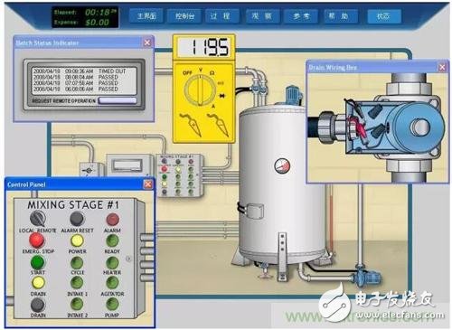
Attachment: The operation mode of an industrial control system after design
Large Diameter Stringing Pulley Block of various type including diameter 508mm, 660mm, 830mm and 916mm,which is specially used for paying off conductors over high voltage steel tower in power line transmission project.It is made of high strength MC Nylon or Alu alloy,etc.we are a professional Chinese exporter of Conductor Pulley and we are looking forward to your cooperation.
Stringing Pulley, Stringing Block, stringing roller, cable block, cable pulley
Yangzhou Qianyuan Electric Equipment Manufacturing & Trade Co.Ltd , https://www.qypowerline.com