1 Introduction
With the rapid development of information technology and the continuous advancement of society, the popularization of high-power LED lighting applications, people's requirements for efficient control and diversification of LED lighting are also increasing, and LED intelligent lighting systems have emerged. The LED intelligent lighting system makes full use of electronic technology, communication technology and computer network technology to organically connect various LED lighting fixtures in the building to achieve effective management and control.
2 Introduction to Ethernet and TCP/IP
Ethernet (Ethernet) is a computer LAN networking technology. The IEEE 802.3 standard developed by IEEE gives the technical standard for Ethernet. It specifies the content of the wiring, electrical signals, and media access layer protocols including the physical layer. Ethernet is the most common LAN technology in current applications. It largely replaces other LAN standards such as Token Ring, FDDI, and ARCNET. The standard topology of Ethernet is a bus topology, but the current Fast Ethernet (100BASE-T, 1000BASE-T standard) in order to minimize conflicts, maximize network speed and efficiency, use switches (Switch) to Network connection and organization, so the topology of the Ethernet becomes a star, but logically Ethernet still uses the bus topology and CSMA/CD (Carrier Sense Multiple Access/Collision Derect) Access) bus contention technology.
The TCP/IP communication protocol set is the most commonly used data transmission protocol for the current network, and it is the well-known Internet Internet main protocol. The basic transmission unit of the TCP/IP protocol is a data packet. The TCP protocol is responsible for dividing the data into several packets and adding a header to each packet (just like adding a envelope to a letter). The header has a corresponding number to ensure that the data can be restored in order at the data receiving end. For the original format. The IP protocol adds the address of the receiving device to each packet header so that the data can find where it is going. (Like the address on the envelope to be written) If the data is lost or data is corrupted during transmission, the TCP protocol will automatically request data retransmission. The IP protocol guarantees the transmission of data and is therefore an address protocol. The TCP protocol guarantees the quality of data transmission and is therefore a transmission control protocol.
3 Introduction to DMX512
Practitioners who know the lighting know this protocol, which is the most widely used lighting communication protocol today. Since USITT (American Theatre Technology Association) increased the Band rate in Colortran's CMX192 from 153.6Kbit/s to 250Kbit/s and 192CH to 512CH (CMX and DMX structures are roughly the same). Mark After Break (MAB) was 4uS when it was first published. In subsequent applications, it was found that there was often a problem of signal refresh and the MAB was extended to 8uS and defined as DMX-512 (1990). Its widespread use is due to its simple structure, low cost, and easy understanding. The major manufacturers have added the DMX512 interface to the product. The successful promotion of the DMX512 protocol and the other greatcomings that everyone is happy to use are the rapid development of computer luminaires for decades and their extensive use in large-scale performances. DMX512 is still a new field of science, with all sorts of wonderful techniques based on rules.
The DMX512 control line uses a 5-pin XLR (sometimes 3-pin) connection device, the female interface is for the transmitter, and the male interface is for the receiver. It is recommended in the specification to use two pairs of wires (4 connectors) to achieve shielding, although only one pair is required. The second pair of wires is used in an unspecified optional situation. It must be noted that some dimmers use these lines to indicate fault and status information. If the dimmer uses a second channel, a specially configured splitter and repeater is required.
The pin assignments for the XLR connector are as follows:
1 shield ground / 0 volt 2 internal conductor (黒) data –
3 internal conductor (white) data +
4 internal conductor (green) alternate data -
5 internal conductor (red) alternate data +
4 Introduction to the industry's mainstream LED control system
4.1: Serial control system, controlled in cascade mode, the signal line of each lamp adopts one-in-one-out mode. Representative products are standard 595 and compatible chips, such as DM134, 135 in Taiwan. Since the chip itself does not generate gradation, if the gradation is required to be generated by the controller, the transmission rate of the system is too high, and the stability of the disturbance is poor in engineering applications.
Advantages: low cost, simple control, no need to set the address, for some projects whose stability and reliability requirements are not very high, this control method can be adopted.
Disadvantages: Too many signal lines usually require 5 signal lines (clock, data, latch, OE, ground).
Due to the one-in-one-out method, when a lamp fails, the normal operation of a string of lights is affected.
The signal line is transmitted by TTL, and the distance between the lamp and the lamp can only be within 1 meter.
For non-standard systems, the luminaire and controller must be products of the same manufacturer, otherwise the two are not compatible.
4.2: Fieldbus control system, which is divided into two categories: DALI bus and RS485 bus.
4.2.1 Introduction to DALI:
In the late 1990s, the lighting industry developed the DALI standard (Digital Addressable Light Interface). This digital addressable lighting interface is designed to replace the traditional 1 to 10V voltage interface for dimming lamp ballasts. DALI defines a standardized digital ballast interface that does not rely on any manufacturer's DALI standard as an IEC60929 international standard, ensuring the interoperability of ballasts from different lighting manufacturers. The DALI component creates a new generation of open digital lighting systems that are flexible, low cost, and distributed. This new open standard has a major impact on the future of lighting control solutions, and it is fundamentally changing the way lighting control solutions based on traditional 1 to 10V voltage interfaces.
The DALI standard has defined a DALI network that includes a maximum of 64 units (independent addresses), 16 groups, and 16 scenes. Different lighting units on the DALI bus can be flexibly grouped for different scene control and management. In practical applications, a typical DALI controller controls up to 40 to 50 lamps and can be divided into 16 groups while being able to process some actions in parallel. In a DALI network, 30 to 40 control instructions can be processed per second. This means that the controller needs to manage 2 dimming instructions per second for each lighting group. DALI is not a true peer-to-peer network. It is a ballast that replaces the 1 to 10V voltage interface. DALI controllers are typically connected to more advanced device networks, such as Ethernet, to support more devices and adequate network bandwidth.
Obviously DALI is not suitable for LED lighting control, a DALI network can only control 21-inch full-color LED lamps. DALI is geared towards traditional lighting control, focusing on the system's static control and reliability, stability and compatibility. The scale of the LED lighting system is far greater than that of the DALI system. It mainly pursues the expressive effect of the lighting art, and properly considers the intelligence of the system. This requires the system to have unlimited expansion capability and high scene refreshing capability.
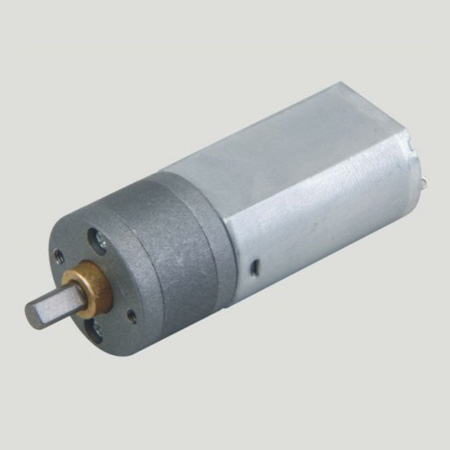
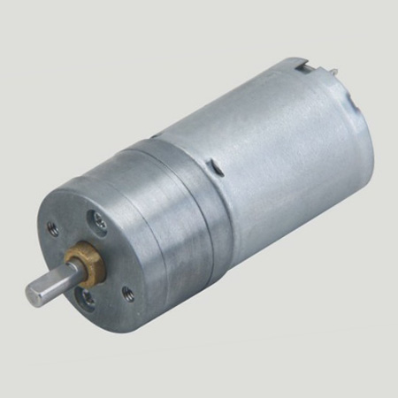
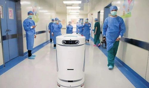
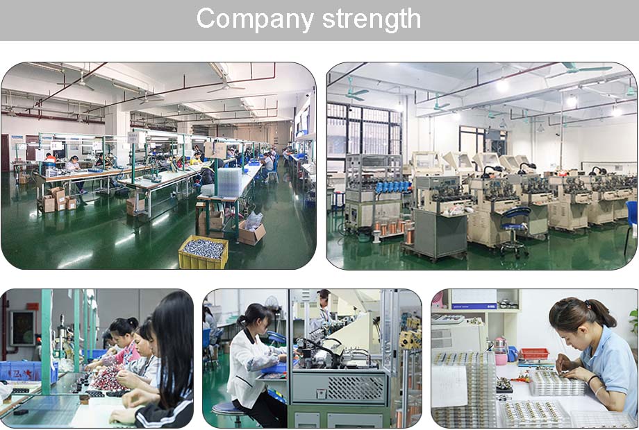
Gear Reducer Motor is a small precision reducer, and the size and specification can be customized below 38mm. Shenzhen shun cheong electrical co., LTD. 15 years engaged in the design, development, manufacture Dc Gear Motor, products applicable to the smart home, widely used in intelligent robot voice interaction, children's education escort robot, intelligent sweeping machine robot, intelligent robot adaptability, independent motor, intelligent medical robot project.
Application field:


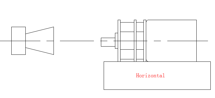
Method of use: the best stable in horizontal plane, installed on the Gear Reducer Motor output shaft parts, cannot use a hammer to knock,knock prone to press into the gear Reducer Motor drive, may cause damage to internal components, and cannot be used in the case of blocked.
Operating temperature range:
Gear reducer motor should be used at a temperature of -10~60℃.
The figures stated in the catalog specifications are based on use at ordinary room temperature catalog specifications re based on use at ordinary room temperature (approximately20~25℃.
If a geared motor is used outside the prescribed temperature range,the grease on the gearhead area will become unable to function normally and the motor will become unable to start.Depending on the temperature conditions ,it may be possible to deal with them by changing the grease of the motor's parts.Please feel free to consult with us about this.
Storage temperature range:
Gear reducer motor should be stored ta a temperature of -15~65℃.
In case of storage outside this range,the grease on the gearhead area will become unable to function normally and the motor will become unable to start.
Service life:
The longevity of gear reducer motor is greatly affected by the load conditions , the mode of operation,the environment of use ,etc.Therefore,it is necessary to check the conditions under which the product will actually be used .The following conditions will have a negative effect on longevity.Please consult with us should any of them apply.
â—Use with a load that exceeds the rated torque
â—Frequent starting
â—Momentary reversals of turning direction
â—Impact loads
â—Long-term continuous operation
â—Forced turning using the output shaft
â—Use in which the permitted overhang load or the permitted thrust load is exceeded
â—A pulse drive ,e.g.,a short break,counter electromotive force,PWM control
â—Use of a voltage that is nonstandard as regards the rated voltage
â—Use outside the prescribed temperature or relative-humidity range,or in a special environment.
â—Please consult with us about these or any other conditions of use that may apply,so that we can be sure that you select the most appropriate model.
when it come to volume production,we're a major player as well .each month,we rurn out 600000 units,all of which are compliant with the rohs directive.Have any questions or special needed, please contact us, we have the engineer group and best sales department to service to you Looking forward to your inquiry. Welcome to our factory.
Gear Reducer Motor
Gear Reducer Motor,Reducer Motor,Gear Reducer Stepper Motor,Dc Reducer Gear Motor
Shenzhen Shunchang Motor Co., LTD. , http://www.scgearmotor.com