Production and debugging of crystal oscillator FM transmitter
In a variety of radio production projects, FM transmitters have been favored by many enthusiasts, but this production involves some high-frequency technology, which makes many beginners in the production debugging such as vibration, interference, frequency, A series of faults such as distortion are upset and even abandoned. This article takes the "FT3S FM transmitter kit circuit" as an example to introduce the reader to the FM transmitter's installation experience and troubleshooting methods. I hope to help the reader.
The simple wireless microphone is a typical example of a wireless transmitter, although it has won the favor of many readers with its "one-fit" advantage. However in the circuit. The serious frequency drift caused by us will be unbearable.
The crystal oscillator used in the circuit of Figure 1 effectively avoids the Achilles heel of "running frequency"; the multiplier amplifier sets the operating frequency to the frequency band that can be received by ordinary radios; and the multi-stage high-frequency amplifier raises the RF power to 80mW. To achieve a longer range of emissions.
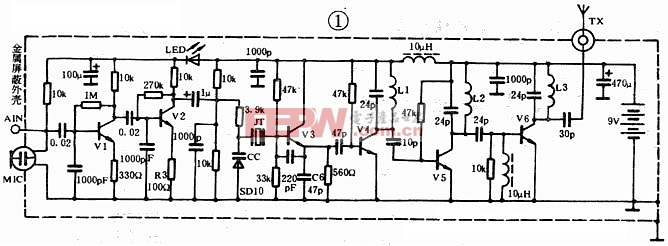
Component selection: All component model parameters are shown in Figure 1;
1. Miniature color code high frequency capacitor is the preferred object, and horizontal installation is used to reduce the influence of lead inductance;
2. JT selects an overtone crystal with a nominal frequency of 49.860MHz. For different output power requirements, other frequency points can be selected according to actual conditions;
3. L1, L2, L3 are the frequency-doubled and high-frequency amplifier resonant inductors. It is recommended to use Φ0.8mm silver-plated wire to be wound on the 4.0mm skeleton. The number of turns is 5T, 4T, 5T respectively; Vl and V2 determine the high frequency. The noise figure and gain of the stage can be selected from low noise tubes with a beta value of about 300, such as C945 and C9014; V3-V5 requires β100-120, fT>500MHz, C1975, C9018, etc. can be used. V6 requires β=100, fT>800MHz, Pc>500mW high-frequency mid-power tube, such as C2581, D40, C2053, when the output power is not high, it can be omitted. The TX can be equipped with a whip antenna or a 1.5m flexible wire. The 75cm length is ideal when the operating frequency is 100MHz.
Production commissioning: All components should be collected before self-made, and the quality and parameters should be carefully tested, and then a suitable circuit board should be designed according to the required volume. All in all, good component quality and proper plate layout are the guarantees to increase the self-made power.
The main debugging steps are as follows:
First, all the components together with the antenna are welded to the printing plate. The requirements for the installation welding process are as follows: the high-frequency part of the component leads are shortened as much as possible; the resistors and capacitors are installed as horizontally as possible, and there is no soldering or de-soldering.
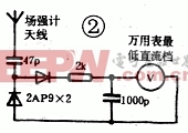
Second, refer to Figure 2 for temporary lap welding a simple field strength meter with debugging.
Third, the transmitter is energized, the voltage is 9V. The field strength gauge lead is 5cm away from the antenna, and the distance between L1, L2 and L3 is repeatedly adjusted to increase the field strength meter maximum, and the resonant capacitance of each stage is adjusted if necessary.
4. By modifying the length of the antenna within a small range, the field strength meter display will continue to increase, and pay attention to the adjustment, the transmitting antenna should avoid contact with the human body or metal.
5. Finally, put the circuit into the metal shield to fix and connect the ground wire to the outer casing.
The above debugging process seems to be relatively simple, but not every reader can successfully complete, and more or less will encounter some troubles. Here are some problems and solutions that often occur in actual production:
1. When using in close range, when the signal with high intensity is picked up, the radio has severe whistling or distortion. This is due to the high gain of the audio amplifier stage and the high sensitivity of the electret microphone. The solution is simple: just increase the resistance of R3 to 820Ω.
2. When inputting the sound source signal with the AIN interface, the radio output sound is small and accompanied by hum. This kind of problem, I believe many friends who have made medium-power high-frequency transmitters have experienced. One of the reasons: due to the use of a rectifying power supply with poor filtering effect, but if the battery is still unable to solve the problem, it may be because the high-frequency signal is too strong, and the amplifying circuit in the sound source (such as CD, Walkma, etc.) , resulting in contamination of the output audio, can be improved by:
1, try to shorten the audio input lead;
2. Connect a 10uH high frequency inductor in series between the transmitter and the audio source.
3. Shield isolation of the sound source;
4. The most direct and effective method should be to reduce the output power or shorten the transmitting antenna. This method can be considered in the case of short-distance transmission and high fidelity.
Third, no vibration or weak oscillation; this fault is manifested in the use of the radio to receive no static noise in the entire band, the output power is small, if the quality of the component can be guaranteed, the following steps can help you to troubleshoot:
1. Connect a 7pF capacitor in parallel with CC (note: the capacitor should not be too large, otherwise you will find that the modulation is invalid);
2, adjusting the oscillation level bias resistor;
3, change the C6 capacity try, if the above method can not be solved, it may be caused by unreasonable component layout, the circuit board can be re-wired.
Fourth, the launch distance is near: This kind of problem is not only due to improper antenna placement, low receiving sensitivity, high usage environment, etc., on the other hand, it is caused by weak oscillation, so it is necessary to refer to the above operation to increase Crystal oscillator output intensity. Another reason may be that the operating frequency of the frequency multiplier is not within the receiving range of the radio. In fact, the radio receives only a weak harmonic signal, which is manifested in the fact that although the field strength meter has a large number of indications, the effective emission distance is small, Up to 100 meters (under normal conditions, with a good radio, the open effective distance is about 500-800 meters). For enthusiasts without frequency measuring instruments, in order to solve such problems, in addition to the resonant inductor, the capacitor should be strictly selected according to the above parameters, and sometimes requires the reader's care and patience, believe in yourself, after many adjustments You will solve all the difficulties.
The hotel projector is a smart projector developed according to the accommodation habits of young people.
As long as the merchant installs the projector, the projector room can be launched to provide the guests with super cool
The perfect movie viewing experience, so that the hotel can not only meet the needs of consumers for accommodation, but also achieve
Movie viewing, entertainment and many other needs.
Projectors used in hotels usually have the following characteristics:
1. The picture is clear and high resolution;
2. The operation is convenient and easy to understand;
3. The sound is loud and the noise is low;
4. The film source is sufficient, and the screen can be projected on the mobile phone;
5. On this basis, the requirements of screen brightness and intelligent system can also be increased.
projector for hotel,hotel laser projector,hotel with projector,projector for hotel,hotel in projector
Shenzhen Happybate Trading Co.,LTD , https://www.szhappybateprojector.com