GPIO, the English full name is General-Purpose IO ports, which is the general IO port. In embedded systems, there are often a large number of external devices/circuits that are relatively simple in structure. For these devices/circuits, there is a need for the CPU to provide control, and some need to be used as input signals by the CPU. Moreover, many such devices/circuits require only one bit, that is, as long as there are two states of on/off, such as the light on and off. Control of these devices/circuits is not appropriate using traditional serial or parallel ports. Therefore, a "universal programmable IO interface", that is, GPIO, is generally provided on the microcontroller chip. The interface has at least two registers, the "General Purpose IO Control Register" and the "General Purpose IO Data Register". Each bit of the data register is directly external to the chip, and the role of each bit in the register, that is, the direction of the signal flow of each bit, can be set independently by the corresponding bit in the control register. Thus, the presence or absence of a GPIO interface is a feature that distinguishes a microcontroller from a microprocessor.
Second, GPIO LCD control programming:The S3C2440 has 130 I/O ports divided into 9 groups of AJ: GPA, GPB, ,, and GPJ. You can set a register to determine whether a pin is used for input, output, or special functions. For example, you can set GPH6 as input, output, or for serial port.
1, through the register to operate the GPIO pin
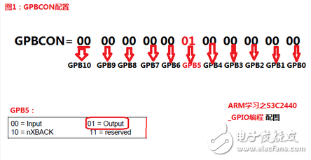
1) GPxCON register It is used to configure the function of the pin. Port A and port BJ are different in function. Each bit in GPACON corresponds to one pin (a total of 23 pins). When a bit is 0, the corresponding reference The pin is the output. At this time, write 0 or 1 in the corresponding bit in GPADAT to make this pin output low level or high level; when a bit is set to 1, the corresponding pin is the address line or used for address control. At this time, GPADAT is reserved. GPACON is usually set to all 1s in order to access the external storage device port BJ in register operation is exactly the same, each bit in PxCon controls one pin, 00 means input, 01 means output, 10 means special function, 11 is reserved.
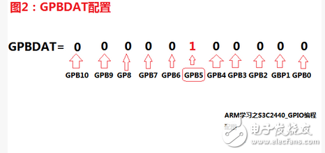
2) GPxDAT register It is used to read and write the pin. When the pin is set as input, read this register to get the level of the corresponding pin is high or low; when the pin is set to output, write this register accordingly Bits enable this pin to output high and low levels.
3) GPxUP register GPxUP, when a bit is 1, the corresponding pin has no internal pull-up resistor; when it is 1, the corresponding pin uses the internal pull-up resistor, the pull-up resistor and the pull-down resistor function when the GPIO pin is out of the The tristate (non-high and low level, but high impedance state, which is equivalent to no chip), its level state is determined by the pull-up resistor and the pull-down resistor.
GPIO control LCD programming example:
[cpp] view plain copy print?
#include
Void delay(int TImes)
{
Int i;
For(;TImes》0;TImes--)
For(i=0;i"400;i++);
}
Int main(void)
{
Int i;
GPBCON =10000000000; /*Configure GPB5 as output (refer to Figure 1)*/
GPBUP =~100000; /*Configure GPB5 pull-up resistor enable (refer to Figure 2)*/
For(i=0;i"10000;i++)
{
/* LED1 is bright*/
GPBDAT = ~100000; /*GPB5 low level*/
Delay(1000);
/* LED1 off*/
GPBDAT = 100000; /*GPB5 high*/
Delay(1000);
}
}
In fact, the above example has a very important problem, that is, the value of other pins is also modified when configuring a pin. In practical applications, it is possible that other pins are performing an operation, and when we configure this way, modifying other pins may cause uncontrollable consequences. How should we operate?
Third, the bitwise AND and bitwise OR operations of the pin configuration:Let's take a look at the above code and use the bitwise AND and bitwise OR operations to modify the effect:
[cpp] view plain copy print?
#include
#define GPF5_out (1"(5*2))
#define GPF5_msk (3"(5*2))
Void delay(int TImes)
{
Int i;
For(;times0;times--)
For(i=0;i"400;i++);
}
Int main(void)
{
Int i;
GPBCON &=~(GPF5_msk); /*GPB5 data clear*/
GPFCON |= GPF5_out; /*Configure GPB5 as output (refer to Figure 1)*/
For(i=0;i"10000;i++)
{
/* LED1 is bright*/
GPBDAT &= ~(1""5); /*GPB5low level*/
Delay(1000);
/* LED1 off*/
GPBDAT |= (1 "5); /*GPB5 high*/
Delay(1000);
}
}
First analyze the two macro definitions:
#define GPF5_out (1"(5*2))
#define GPF5_msk (3"(5*2))
GPF5_out is defined as 1 left shifted to 10, becomes: 1000,0000,000, GPF5_msk is defined as 3 (ie, binary 11) is shifted left by 10, becomes: 1100, 0000, 0000.
Statement GPBCON &=~(GPF5_msk): /*GPB5 data clear*/:GPF5_msk performs non-operation into: 0011, 1111, 1111, any number with which it is operated, the highest two (the result is 00xx, Xxxx, xxxx, x are unknown), so that the corresponding bit clearing effect can be achieved.
Statement GPFCON |= GPF5_out: Any number is ORed with GPF5_out(1000,0000,000). The highest bit must be 1 and become 1xxx, xxxx, xxx. Adding the 0 that is not shown above, you can configure port 5 of this pin as the input pin, 01.
Similarly, configuring GPBDAT to a low level allows it to operate with a non-(100000 - "01111) left shift of 5, and the low level of the port is obtained, and the high level is the same.
Mr Fog Max 3.5ml Disposable Pod Device
The Mr fog Max Disposable Device comes pre-filled with 3.5ml's of 5% nic salt e-liquid and comes packaged as a Disposable Vape. Allowing the user to enjoy a flavorful vape with zero up keep, and requiring a simple trash once the device has been used up. Each Mr Fog Max Disposable Device features an estimated 800-1000 puffs, and has a high capacity internal battery which is to be disposed of once the life cycle is complete.
Mr Fog Max 3.5ml Disposable Vape Features:
* Disposable Device
* 1 Device Per Package
* 5% nic
* Contains 3.5mL e-Liquid
* 800 - 1000 puffs
* 5 JUUL Compatible Pods
* High Capacity Internal Battery (600mAh)
Mr fog Max Disposable flavors:
Mr fog Max Disposable Mango Pineappl
Mr fog Max Disposable Apple Berry
Mr fog Max Disposable Strawberry Watermelon Kiwi
Mr fog Max Disposable Rainbow
Mr fog Max Disposable Blue Raspberry Lemon
Mr fog Max Disposable Banana Ice Cream
Mr fog Max Disposable Blueberry On Ice
Mr fog Max Disposable Grape
MR FOG MAX,E-Cigarette Vape Pens,Rechargeable E-Cigarette,E-Cigarette Vaporizer Pen,Electronic Cigarette From Pocket
Shenzhen Ousida Technology Co., Ltd , https://www.osdvape.com