Controller Area Network (CAN) is a serial communication protocol bus for real-time applications. It can transmit signals using twisted pairs. It is one of the most widely used fieldbuses in the world. The CAN protocol is used to communicate between various components in a car, replacing expensive and bulky distribution harnesses. The robustness of the protocol extends its use to other automation and industrial applications. Features of the CAN protocol include integrity of serial data communication, real-time support, transfer rates up to 1Mb/s, simultaneous 11-bit addressing, and error detection.
CAN system composition
The CAN bus user interface is simple and easy to program. The network topology uses a bus structure. The network structure is simple, the cost is low, and the passive tap connection is adopted, and the system reliability is high. Each network node is connected through a CAN bus to form a multi-master controller area network (CAN). The transmission of information is done by the CAN controller using the CAN communication protocol. Each network node generally performs on-site data acquisition and CAN-based data transmission for an intelligent node with a microcontroller. The node can use a microcontroller with a on-chip CAN controller, or a general-purpose microcontroller plus A separate CAN controller to complete the node function. The transmission medium can be twisted pair, coaxial cable or fiber. If it is necessary to further improve the anti-interference ability of the system, it is also possible to add optical isolation between the controller and the transmission medium, and the power supply adopts measures such as a DC-DC converter. This makes it convenient to construct a real-time distributed measurement and control system. The microcontroller, or a general-purpose microcontroller plus a separate CAN controller to complete the node function. The transmission medium can be twisted pair, coaxial cable or fiber. If it is necessary to further improve the anti-interference ability of the system, it is also possible to add optical isolation between the controller and the transmission medium, and the power supply adopts measures such as a DC-DC converter. This makes it convenient to construct a real-time distributed measurement and control system.
Physical interface of the CAN bus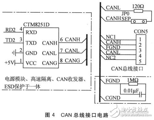
The CAN transceiver PCA82C250 is used as an interface between the CAN controller and the physical bus to provide differential transmission capability to the bus and differential reception capability to the CAN controller.
Generally, a photocoupler is added between the driving chip and the CAN controller to increase the anti-interference ability. The speed of the CAN bus will be determined by the speed of the optocoupler. For example, with 4N27 optocoupler, because its response speed is relatively slow, the bit speed of CAN network can only reach tens of Kbit/s. If the 6N137 high-speed optocoupler is used, the CAN network speed can be as fast as that of the resistor network. In addition, the design of the physical layer should pay attention to the terminal impedance matching of the cable, which directly affects the normal operation of the CAN bus and network performance. Generally, 120Ω resistors are connected in parallel across the CAN bus.
How the CAN bus works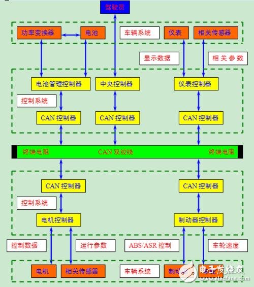
The CAN bus uses serial data transmission, which can run on a 40m twisted pair at a rate of 1Mb/s, or it can be connected using fiber optic cable, and the bus protocol supports multi-master controllers on this bus. CAN and I2C bus are very similar in many details, but there are some obvious differences.
When a node (station) on the CAN bus transmits data, it broadcasts it to all nodes in the network in the form of messages. For each node, whether the data is sent to itself or not, it is received. The 11-character character at the beginning of each group of messages is an identifier that defines the priority of the message. This message format is called a content-oriented addressing scheme. In the same system the identifier is unique and it is not possible for two stations to send messages with the same identifier. This configuration is important when several stations compete for bus reads at the same time.
When a station wants to send data to other stations, the CPU of the station sends the data to be sent and its own identifier to the CAN chip of the station, and is in the ready state; when it receives the bus assignment, it changes to send the message. status. The CAN chip sends the data according to the protocol and is organized into a certain message format. At this time, other stations on the network are in the receiving state. Each station in the receiving state detects the received message and determines whether the message is sent to itself to determine whether to receive it.
Since the CAN bus is a content-oriented addressing scheme, it is easy to build a high-level control system and configure it flexibly. We can easily add some new stations to the CAN bus without having to modify them in hardware or software. When the new station provided is a pure data receiving device, the data transfer protocol does not require a separate portion to have a physical destination address. It allows the distribution process to be synchronized, ie when the controller on the bus needs to measure data, it can be obtained online, without having to have its own separate sensor for each controller.
CAN bus features
(1) It has the advantages of strong real-time performance, long transmission distance, strong anti-electromagnetic interference capability and low cost;
(2) It adopts two-wire serial communication mode, which has strong error detection capability and can work in high noise interference environment;
(3) With priority and arbitration functions, multiple control modules are connected to the CAN-bus through the CAN controller to form a multi-host local network;
(4) The message can be received or blocked according to the ID of the message;
(5) Reliable error handling and error detection mechanisms;
(6) After the sent information is destroyed, it can be automatically resent;
(7) The node has the function of automatically exiting the bus in case of serious error;
(8) The message does not contain the source address or the destination address, and only the identifier is used to indicate the function information and the priority information.
Hf Drivers - Ferrite,Titanium Tweeter Driver,Titanium Compression Drivers,Line Array Speaker Driver
NINGBO BOILINGSOUND ELECTRONICS CO.,LTD , https://www.tweeterspeaker.com