1 Introduction
This article refers to the address: http://
There are many bus technologies available today. In terms of cost, the cost of RS-232/485 is lower than that of CAN; in terms of speed, industrial Ethernet is also good. Why is CAN only favored in automotive electronics?
In terms of cost, CAN is higher than UART and RS-232/485, but lower than Ethernet. From real-time: CAN's real-time performance is higher than UART and Ethernet. In order to ensure security, the vehicle communication protocol is based on Periodically active transmission, whether it is CAN or LIN, the message with high real-time requirements has a transmission period of less than 10ms (there are several such messages per car), and the engine, ABS and transmission have several such messages; In terms of reliability, CAN has a series of accident safety measures, which are not available in UART and Ethernet. Multi-point redundancy is also difficult to implement with UART (point-to-point transmission) and industrial Ethernet (short data transmission distance), so CAN After the emergence, due to price reasons, the most widely used place is not the car, but the cost-insensitive industrial control and medical equipment, such as: industrial DEVICENET, SDS, CANOPEN, medical MRI and so on. As for the generation of industrial Ethernet, its background is inseparable from the popularity of personal PCs. Now PCBASED in industrial control is an example, but car control can not use a PC, to meet the requirements of car control, cost Not allowed. The transmission process of LIN is only 20Kbps, which obviously cannot be used as an independent car bus control requirement. Generally, it only cooperates with CAN to assist in the car.
Vehicles are a special application environment, and the continuous improvement of vehicle automation has put forward higher requirements for vehicle instruments. Traditional magnetic and magnetic instruments have become less and less suitable for the development of modern intelligent vehicles, and virtual instruments have The characteristics of interaction, intelligence and ease of expansion are widely recognized. This topic requires the design of a set of virtual instruments for a car, the host computer uses a PC104 embedded microcomputer based on the RTOS development environment. As the most important subsystem of the virtual instrument, the vehicle environment data acquisition system requires data acquisition and communication functions, and has high timeliness and reliability. According to the author's experience, this paper introduces the method of designing the vehicle data acquisition system with Philips' high-performance single-chip microcomputer P80C592, focusing on the system design and CAN communication programming.
2 System Introduction
According to the design requirements, the system mainly completes the processing of the sensing signal and the data acquisition of the working condition of the vehicle and sends the data to the host computer through the CAN bus. It is required to process 16 analog signals, 4 frequency signals and 32 extended IO signals, and collect parameters. Mainly: engine oil pressure, water temperature, oil temperature, speed, vehicle speed, transmission oil pressure, fuel tank oil and grid voltage, door status, turn signal indication, vehicle body super wide indication and vehicle environment warning, etc., signal form There are voltage, frequency, and switching signals, and the signal frequency ranges from 0 to 6KHZ.
2.1 System hardware structure design
Figure 1 shows the hardware structure of the system. The core device used in the system is Philips' 8-bit high-performance microcontroller P80C592, which is fully compatible with the standard 80C51. Its main features are: built-in CAN controller capable of DMA data transfer with internal RAM; 4 capture ports and 2 standard 16-bit timer/counter; 8-channel ADC input with 8 analog inputs; 2 x 256 bytes in chip RAM and a Watch Dog.P80C592 on-chip CAN controller can fully implement CAN protocol, reducing System connectivity enhances diagnostics and monitoring capabilities. The digital-to-analog converter uses a 12-bit AD1674A with a resolution of 0.02% and a conversion time of 25uS. In order to improve the system's anti-jamming capability, optical isolation is used between analog-to-digital circuits and between the system and the CAN bus, and the simulation is performed. The circuit and digital circuit are designed as two separate PCB boards, and the two boards are connected to form a complete system.
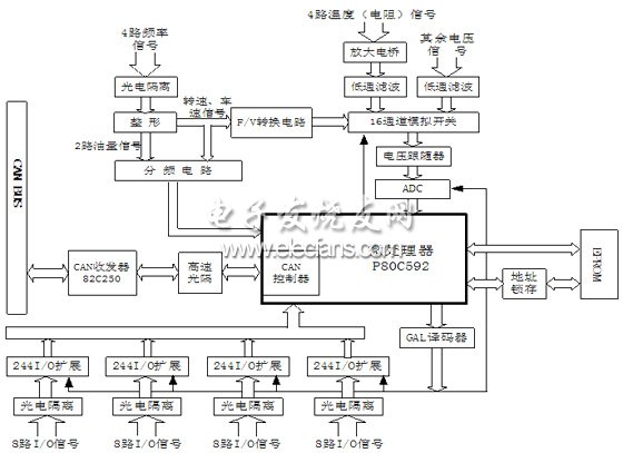
Figure 1 system hardware structure diagram
Hardware working process: temperature, pressure and voltage signals are sent to 16 analog switch MAX306EP through relevant processing circuit, and A/D conversion is performed by voltage follower circuit input AD1674A. In order to improve reliability and stability, the system does not use microcontroller. In the chip ADC converter. Under the control of the program, the 16 channels are sequentially gated, and the collected data is encapsulated in the CAN controller in the CAN controller, and transmitted by the transmitting port to the CAN bus via the optical isolation and transmitter. The oil quantity signal is sent to the capture port of P80C592 for frequency measurement after photoelectric isolation, shaping and frequency division. The speed vehicle speed signal is divided into two paths after being shaped, one is divided by frequency divider circuit to MCU capture port, and the other is F/V converted. Post ADC sampling. Access to the ADC and I/O expansion ports is controlled by the programming logic output of the GAL decoder.
2.2 Frequency signal measurement
Frequency signal measurement is a design difficulty of this system. In this subject, the sensors used for different models are different. Therefore, there are two methods for processing the speed and speed signal: First, when the output frequency range is 0. -100HZ contact sensor, using CS289 frequency conversion chip, the frequency signal is converted into a 2.2~7.2V voltage signal and then sent to the ADC for acquisition; the second is when the output signal frequency range is 0~3000HZ non-contact sensor The frequency is measured by the pulse counting method of the capture port of the single chip microcomputer. In order to improve the versatility of the system, the two methods can be used at the same time, and the data obtained by which method is adopted is set by the microcomputer software. Figure 2 is a circuit diagram of the F/V conversion circuit.

Figure 2 F / V conversion circuit diagram
The CS289 is a single-chip high-precision dedicated speed measurement chip produced by Cherry Company of the United States, which has a good linear output in the temperature range of -400 to +850. It can be used not only for F/V, V / F conversion, but also as a function generator and a moving magnetic instrument driver. The F/V conversion circuit composed of the same has few peripheral components, easy debugging, and stable and reliable operation. As shown in Fig. 2, the shaped rotational speed pulse signal is transmitted through the filtering network and the limiting input CS289 pin 10, and the voltage signal is output by the eighth pin, which is filtered to eliminate possible power frequency interference and sent to the sampling circuit. In this circuit, the relationship between the output voltage and the input frequency is determined by the following equation: The upper computer calculates the frequency value based on the linear relationship. In order to ensure that the F/V conversion has a sufficiently high linearity, the value should be reasonably selected.
3 system software design
The system software mainly completes three tasks: 1. sampling and solving the sensor signal; 2. transmitting the collected data to the upper computer when the upper computer requests the data; 3. when receiving the self-test command of the upper computer, uploading the data to complete the sensor signal Switch to standard signal. The program flow is shown in Figure 3.
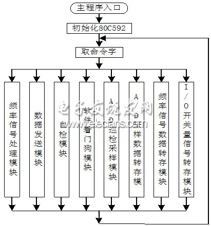
Figure 3 program flow diagram
The main program uses modular programming. The fault self-diagnosis function is one of the important features of the virtual instrument. For this purpose, three sets of standard signals are designed in the data acquisition system, namely the frequency signal, the voltage signal and the resistance signal. The main function of the self-test module is: when receiving the upper position After the self-test command issued by the machine, the microcontroller disconnects the sensor input, the standard signal is connected to the data acquisition system, and the obtained data is uploaded to the host computer for comparison with the standard value to determine whether the fault point is a sensor system or a data acquisition system. If the self-test passes, it indicates that the data acquisition system is working properly. The data transmission module mainly realizes data communication to the upper computer, and the system is designed to send data packets to the upper computer every 20 milliseconds. The data dumping module completes the operation of writing various data in the slice main RAM. In order to distinguish the data type, it is necessary to add a corresponding type identification code in the data block, and the code is defined by the user layer protocol. The A/D sampling module controls the system sampling process and reads each 12-bit sample data into the specified RAM unit twice.
The frequency signal processing module completes the measurement of the capture port frequency, and the basic idea is that, in one cycle time of the signal under test, the two pulse falling edges respectively start and stop the timer T2 counting, and the reciprocal of the difference between the two counting values ​​is For the frequency value, this module only needs to calculate the difference, and the frequency value is solved by the upper computer. 3.1 CAN controller programming
One difficulty in the design of this system software is the programming of CAN. The CAN program modules processed by this system are: CAN initialization subroutine, CAN interrupt program and CAN data transceiver subroutine.
CAN is an abbreviation of Controller Area Network and is an internationally standardized serial communication protocol. In the current automotive industry, various electronic control systems have been developed for safety, comfort, convenience, low pollution, and low cost. Since the types of data used for communication between these systems and the requirements for reliability are not the same, there are many cases in which a plurality of buses are formed, and the number of wire harnesses also increases. In 1986, the German electric company Bosch developed a CAN communication protocol for automobiles in order to meet the need to "reduce the number of wire harnesses" and "high-speed communication of large amounts of data through multiple LANs". Since then, CAN has been standardized by ISO11898 and ISO11519 and is now the standard protocol for automotive networks in Europe.
The basic characteristics of the CAN bus:
*CAN protocol abolishes the traditional station address coding, uses data communication data blocks for programming, and can work in multiple master mode.
*CAN adopts non-destructive arbitration technology. When two nodes transmit data to the network at the same time, the node with lower priority actively stops data transmission, and the node with higher priority can continue to transmit data without affecting, effectively avoiding bus conflict. .
*CAN adopts short frame structure, and the effective byte of each frame is 8 (CAN specification 2.0A), the data transmission time is short, the probability of interference is low, and the time of retransmission is short.
*CAN each frame of data has CRC test and other error detection measures to ensure high reliability of data transmission, suitable for use in high interference environments.
*Applicable to the communication network between the field device and the instrument or between it and its upper device. It can be configured in a unified way, interoperate, and the control function is dispersed to the lowest level.
* The CAN node has the function of automatically turning off the bus in case of serious error, and cuts off its connection with the bus so that other operations on the bus are not affected.
*CAN can transmit and receive data in point-to-point, point-to-multipoint (group) and global broadcast centralized mode
* CAN bus direct communication distance up to 10km/5Kbps, communication speed up to 1Mbps/40m.
* Adopt NRZ-Non-Return-to-Zero encoding/decoding method and adopt bit filling (insertion) technology.
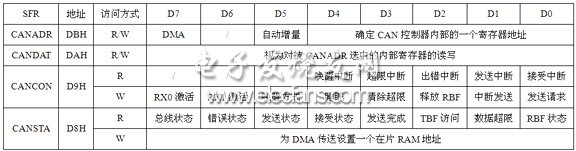
The CAN controller appears as a CPU memory map peripheral. The data transfer between the CPU and CAN controller of P80C592 is realized by four special function registers, namely: CANADR, CANCON, CANSTA and CANDAT. Through these four special function registers, the CPU can access any register inside the CAN controller. (Address 0~29) and DMA logic. Table 1 gives a brief description of the functions of these four SFRs, where the CANCON and CANSTA read and write operations have different meanings.
Table 1 SFR function brief
The CAN controller initialization (Figure 4) is a very important subroutine in CAN communication. The reasonableness of the program will directly affect the entire communication process. The initialization of the CAN controller must first set the "reset request" bit of the CAN control register. Setting the "reset request" does not affect an ongoing transmit and receive operation. In particular, only when the reset request is asserted. The register with CAN internal address 4-8 can be accessed. After the reset operation is finished, the position must be set to 0 to keep the settings made and return the CAN to the working state.
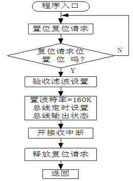
Figure 4 An important subroutine in CAN communication
Both the P80C592 and its on-chip CAN controller have interrupt registers, and the difference between the two must be noted. The CAN interrupt subroutine (Fig. 5) first reads the CAN interrupt register (IR) to determine the type of interrupt, and then transfers to the corresponding operation. If the receive buffer is full and the first byte of another message needs to be stored, the data overrun is set. In this case, the overrun should be cleared and the receive buffer should be released and the data request resent. After the data is transferred to the RAM area in the data accepting subroutine, the accept buffer should be released in time to prepare for receiving the next frame of data.
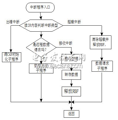
Figure 5 CAN interrupt subroutine
The data transmission subroutine is shown in Figure 6. When the CAN controller sends data to the bus, it first writes the first address of the data stored in the main RAM of the chip to CANSTA, and then reads the value of CANSTA.6 (the operation of reading CANSTA is actually for CAN) the controller reads the internal status register, CANSTA.6 bit error display is, when at least one CPU bus error counter counts the alarm limit, the CAN controller bit is set.) If the error detection is performed CAN the initialization subroutine, if normal, the reception state and continues to detect the state of the transmission buffer, when the transmission condition is satisfied and written into the transmit buffer address set in the DMA control bit CANADR, then the DMA transfer is enabled, the data from the RAM copy field the transmit buffer, a transmission request bit is set after the start of data transmission.
4 Conclusion
P80C592 with high-performance data acquisition module and AD1674A vehicle environment data acquisition system has a high cost, now the system has been put into the trial stage, running in good condition. CAN bus is ideal for distributed control or timely control of the serial communication network, this project only involves data acquisition, control and auxiliary vehicles if the extension of important data backup function on this basis, the system will have a wider application.
ZGAR GenkiIppai Pods 5.0
ZGAR electronic cigarette uses high-tech R&D, food grade disposable pod device and high-quality raw material. All package designs are Original IP. Our designer team is from Hong Kong. We have very high requirements for product quality, flavors taste and packaging design. The E-liquid is imported, materials are food grade, and assembly plant is medical-grade dust-free workshops.
From production to packaging, the whole system of tracking, efficient and orderly process, achieving daily efficient output. WEIKA pays attention to the details of each process control. The first class dust-free production workshop has passed the GMP food and drug production standard certification, ensuring quality and safety. We choose the products with a traceability system, which can not only effectively track and trace all kinds of data, but also ensure good product quality.
We offer best price, high quality Pods, Pods Touch Screen, Empty Pod System, Pod Vape, Disposable Pod device, E-cigar, Vape Pods to all over the world.
Much Better Vaping Experience!


ZGAR GenkiIppai 5.0 Pods,ZGAR GenkiIppai Pods 5.0,ZGAR GenkiIppai Pods 5.0 Pod System Vape,ZGAR GenkiIppai Pods 5.0 Disposable Pod Vape Systems, Japanese culture style
Zgar International (M) SDN BHD , https://www.zgarvape.com