Industrial Control Systems (ICS) is the foundation of industrial production. The security of ICS is directly related to the stability of economic and social development and national security. Different from other computer systems, there are a large number of private non-standard non-public agreements in industrial control systems [1]. Communication protocols are used as the basis for information exchange between industrial control devices. Their security is an important part of the security of industrial control systems. Protocol analysis technology is of great significance for improving the security of industrial control systems.
Traditional protocol reverse analysis methods require a lot of time and manpower. At present, there are mainly two methods in the field of protocol automation inverse analysis: one is based on network packet sequence analysis methods, and the other is based on program execution path methods. The method based on network message sequence analysis is better for text protocol processing, but lacks semantic analysis of the protocol for the protocol [2], especially in the face of multi-layer encapsulated application layer protocols that are common in industrial control environments. ; And based on the implementation of the trajectory method based on dynamic binary program analysis, including Polyglot, AutoFormat, Tupni, Prospex and other methods, these methods require sample coverage, the need to repeatedly run the program debugging [3], but the code during debugging The direct modification severely damaged the stability of the industrial control system. Although the analytical results of this method are more accurate, it is not suitable for the industrial control system to require high stability and high real-time conditions.
Aiming at the above problems, this paper proposes a method of industrial control protocol analysis based on static binary analysis. This method accesses binary files in a read-only manner, which not only can obtain the protocol semantics, but also can guarantee the stability of the industrial control system. The analysis result can be used as the input of the fuzzing test module in the communication protocol robustness test platform in addition to providing the protocol information, so as to solve the problem that the ordinary fuzzing system cannot specifically construct the test sample in the face of the private protocol.
1
Overall design
This article introduces the analysis method of the industrial control protocol as a subsystem of the industrial control system robustness test platform. The structure of the protocol robustness test platform is shown in Figure 1.
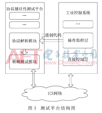
In today's ICS, the Windows operating system based on the x86 platform is increasingly widely used. Therefore, the method in this article is mainly implemented for the Windows operating system, and the disassembly engine uses Hex-Rays' IDA Pro. IDA Pro is a powerful static binary analysis tool that provides a feature-rich IDC library (a native scripting language for IDA Pro) and a Software Development Kit (SDK) [4].
The protocol resolution subsystem mainly includes the following sub-modules: a file scanning sub-module, a protocol extraction sub-module, and a format processing sub-module. Among them, the protocol analysis module includes a data preprocessing phase, a cross reference analysis phase, a protocol frame reconstruction phase, and a semantic extraction phase; the output of the format processing module can be used as the input of the test platform fuzzing module, and is the construction of the fuzzy test sample data. For reference, it can also be used as the input of the test platform interaction module to provide users with graphical results. The sub-module structure of the protocol analysis module is shown in Figure 2.

2
File scanning module
The scanning target of the scanning module is the industrial control software such as configuration software running on a general-purpose computer. Generally, industrial control software is relatively bulky and consists of many functional modules. However, protocol analysis only requires one of the communication modules. Performing protocol analysis algorithms on all functional modules of ICS software will not only increase the time overhead, but also reduce the accuracy of analysis. The main function of the scanning module is to locate the object of the protocol analysis and to filter out operations that are not related to the communication for the protocol analysis module.
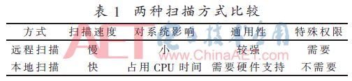
The file scanning sub-module has two implementation modes. One is remote scanning. The scanning process runs on the test platform. The filtering operation is realized by remotely reading the ICS software executable file on the engineer station or operator station and performing analysis; The hardware-based card is used to perform the scanning process locally on the IPC through the USB interface, and the scan results are collected and fed back to the test platform. The difference between the two implementation methods is that the scanning process runs in different locations. Remote scanning has no performance impact on the IPC, but it requires the IPC to open the file access rights. The local scanning may occupy a certain amount of CPU time during the scanning process. The extra permissions and their specific differences are shown in Table 1.
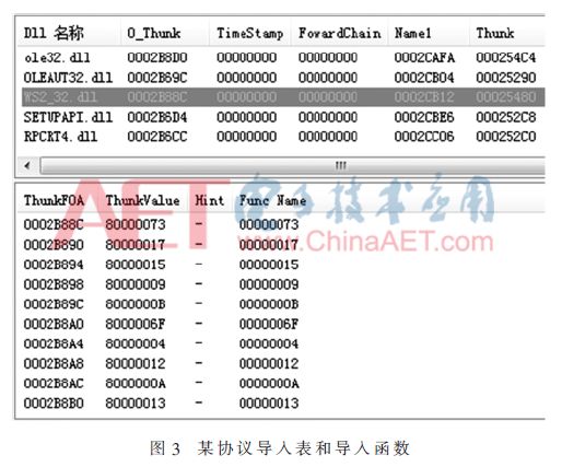
The above two implementation methods have no difference in the essence of the algorithm. They all read and predict the operations involved in the DLL by reading the import table of the Dynami Link Library (DLL) file and importing the function table. In general, the TCP protocol communication involves the import of the send and recv functions in WS2_32.dll. The UDP protocol requires the import of the sendto and recvfrom functions in WS2_32.dll [5], and a protocol communication module searched by the scan module. The import table and import functions are shown in Figure 3. In addition, by scanning and filtering the system calls such as WriteFile can also find some of the package and packet functions encapsulated by the ICS software itself, and these functions can also be used to analyze industrial control protocols that are not based on TCP/IP, such as the industrial control protocol based on the COM serial port. Protocol analysis based on network traffic cannot be done.
3
Protocol extraction module
The protocol resolution module is based on IDA Pro's IDC script and SDK, providing protocol resolution services in the form of IDA scripts or IDA plug-ins.
3.1 Data Preprocessing
The types of software used by ICS are complex and vary greatly in implementation structure. Some vendors do not strictly follow the principles of modular design when designing software. Software communication modules are not independently packaged in DLLs, but are mixed with other function codes. Put DLLs together, even in multiple DLLs. Data preprocessing For this case, by reading the assembly code disassembled by IDA Pro, the functions in the DLL are marked and the functions that are not related to the communication process are eliminated. For functions that cannot be determined, select Hold processing.
The screening algorithm uses two kinds of standards at the same time. The first standard is based on upward code cross-referencing and uses the hierarchical structure of function calls. The second standard idea is derived from the commonly used taint algorithm in dynamic binary inverse analysis. Later based on data cross-reference implementation, used for static binary analysis scenario [6].
The definition of the tuple f(N,F) represents a function in the DLL, where N is the name of the function and F is the token, which is enumerated from UNKNOW, STAY, and DELETE.
The basic flow of the screening algorithm is as follows:
(1) Add the functions (including DllMain, exported functions, and internal functions) in the target DLL to the function set S. The initial flags F are all DELETEs.
(2) Using the first standard, the address of the function that sends and receives data packets is the bottom-level starting point, using the IDC functions Rfirst and Rnext to access all its reference functions fn(N,F), and the fn(N,F) Flag F is set to STAY.
(3) Perform step (2) iteratively until all function flags that reference the start function are set to STAY.
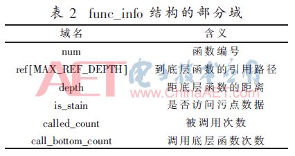
(4) Using the second criterion, search the memory location of the memory area marked as a stain in reverse order with the memory buffer used in the parameter of the underlying function in step (2) as the stain source, if there is fn(N,F) In the referenced taint memory area, the flag F of fn(N,F) is set to STAY; if there is an assignment operation with the smut memory left-valued in the code, the memory area as the right value is also marked as tainted memory. And record the relationship between the spread of the stain, the system maintains a smut relation data structure func_pollut for each fn (N, F) in S, the data structure content shown in Table 2; if the function fn (N, F) does not explicitly refer to the stain If the memory area and other memory locations it references cannot directly determine whether it is related to the dirty memory, set the flag F of fn(N,F) to UNKNOW.
(5) Iteratively performs step (4). Enumerate the functions in the set S, remove all function elements that mark F as DELETE, and the set S at this time is the target set to be processed.
3.2 Cross-reference analysis
From the software reverse engineering point of view, the underlying functions that are referenced by different upper-level functions are more versatile, and the higher the degree of encapsulation, the more often they are handled in functions in the software packages that encapsulate and parse the protocol. A certain type of general-purpose frame structure, such as frames carrying data payloads and heartbeat frames; being referred to by different upper-level functions, or even having only referenced functions in a certain place, encapsulated and parsed by the protocol In the software module, some control operations such as connection establishment and communication peer authentication are often completed. This type of frame belongs to the control frame.
The main task of the protocol analysis system in the cross-reference analysis stage is to call the IDC function to obtain the cross-reference information and store the information in the data structure func_info. The function dependency of a protocol is shown in FIG. 4 . The function type is inferred by counting the obtained reference data, and the inference result is input as a protocol frame classification stage. The contents of the structure func_info are shown in Table 2.
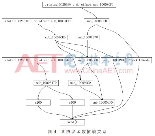
The demarcation value used for function type inference is related to the complexity of the protocol. In general, the distance between the function related to the control frame and the underlying function is short, the number of times of being called is small, and the number of calls to the underlying function is many times. After the experimental comparison, the specific demarcation point value is the distance from the underlying function is 2, the number of calls is 1, the number of calls to the underlying function is 3 to 5, the system has a higher accuracy, the system reserves the configuration interface here The user can specify the demarcation point value according to the protocol complexity. In addition, IDA Pro's own WinGraph32 application system can obtain more intuitive function-dependent graphics. The dependency graph is directly presented to the user as an output result of the module. The user can specify the key analysis module or correction for the system according to his own judgment. Systematic speculation results in improved resolution.
3.3 Protocol Frame Reconstruction
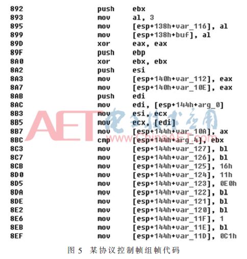
The functional dependencies obtained in the previous two phases of the protocol frame reconstruction phase and the presumption of the function type are referenced. The function code characteristics are determined, and the frames existing in the target protocol are reconstructed and classified. The function code features involved in the algorithm mainly include whether the distance from the underlying function is 1, whether there are more magic number assignment operations, and whether the length is fixed. A typical control frame framing operation is shown in FIG. 5, and it can be seen that there are obviously many magic number assignment operations.
The algorithm flow of frame reconstruction is as follows:
(1) The frame set A is initialized to an empty set, and the functions with the flags F and STAY and UNKNOW in the function set S are arranged in ascending order according to the route_len field value of the func_info structure obtained in the previous stage, and stored in the sequence table D.
(2) Take a function fn(N,F) from the sequence table D. If the function distance of fn(N,F) is 1, check the underlying function call parameters and retrieve the buffer length parameters in the code of this function. Data reference, if the buffer length is fixed, and the value is not the same as the frame length of all fixed-length frames in the set A, a fixed-length frame is created, the frame length is the length of the buffer, and the frame is added to the collection A.
(3) If it cannot be determined in step (2) that the buffer length is a fixed value, an indefinite length frame is created, and the frame is added to the set A.
(4) For the newly added frame in step (2) or step (3), retrieve the code from the underlying function call address up until the function header or another low-level function call, directly to the field for all magic assignment operations. The length and magic value are recorded in the corresponding structure of the newly added frame; for the variable assignment operation, the field value is temporarily replaced with a symbol after the field length is recorded. Count the number of magic values ​​H and the number of variable assignments B. If H > 2B, mark this frame as a control frame, otherwise mark it as a data frame.
(5) If the fn(N,F) function distance is not 1, retrieve the function code, record all the magic number assignments to the smut memory block, and access the func_pollut structure after the search, passing the function number where the pollution source is located. The collection A retrieves the corresponding frame structure and replaces the symbols in the corresponding positions in the frame structure with magic values.
(6) Repeat step (2) until all functions in sequence table D are accessed.
After the execution of the algorithm, the frame in the set A is the initially constructed protocol frame. The frame structure at this time records the preliminary field structure and the constant field value.
3.4 Semantic extraction
The semantic information of the protocol mainly includes delimiters, keywords, check fields, length fields, indication fields, etc. The semantic information of the protocol frames can be extracted by retrieving whether the binary codes of the fields of the processing protocol frames have relevant features [7]. . For example, the check field is usually accompanied by a large number of shift operations; the key and separator will involve constant assignment operations. The main difference is that the key is usually general data, and the separator value can usually be mapped into an ASCII table. The specific characters; the length field also involves a constant assignment operation, but for the same type of frame structure, different call point constant values ​​are generally different.
For some code segments that cannot extract more significant features, the system selects the strategy to directly extract the relevant binary code, and records the association relationship between the binary code segment and the corresponding protocol field in the data structure after being dumped into the file.
3.5 Format processing
The protocol format obtained by the above process may have redundancy. The same variable length frame is recorded as two or more frames due to different values ​​of individual fields. In addition, the logical relationship information between frames is not complete. In the format processing module, the system implements de-redundancy by comparing the known semantics of the frames in the set. Although the length and some field values ​​are not exactly the same between indefinite long frames, the known semantic repetition rate is only found through semantic comparison. If the threshold is exceeded, it is determined that both frames should be the same type of frame, and the two are combined.
Finally, the system formats the frames in the collection and outputs the protocol information to a result file in a standard format. The fuzzy test module reads the file to obtain the frame structure and semantics of the protocol, and constructs test cases for the protocol structure.
4
Experiments and analysis
The main part of the protocol analysis system, semantic extraction and formatting are implemented in C language. Data preprocessing and cross-reference analysis are implemented by IDC scripts. The reconstruction of protocol frames is achieved by calling IDA Pro SDK in C language.
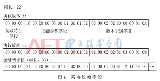
In the experiment, the independently implemented system was applied to the analysis of the driver of a proprietary protocol provided by Kingview Software. Part of the protocol format was successfully obtained, and the resulting protocol format was used to achieve simple interworking with the device, demonstrating the correctness of the method. Sex and effectiveness. After parsing, the protocol considers the identification of the protocol version when the connection is established. The protocol frame obtained from the experimental analysis is shown in Figure 6.
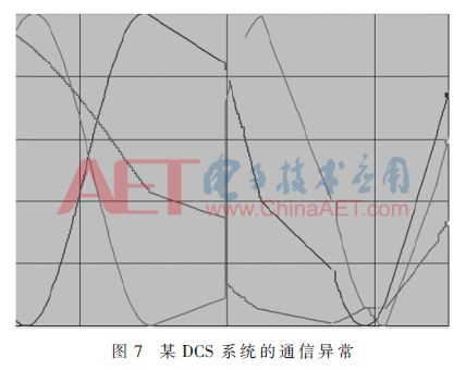
In addition, in the penetration test of a DCS system, this protocol analysis system is used as a module of the protocol robustness test platform, which provides a reference for the fuzzing test module. The fuzzy test module takes the output of the protocol analysis system as an input. According to the analysis result, 80 sets of test cases are generated for the application layer protocol of the DCS system. In the test process, the communication abnormality of the target system is caused several times, and the method is proved. Practicality. An example of the fuzzy test result is shown in Fig. 7. The curve in the figure is the sinusoidal data stream carried in the system heartbeat frame. After the start of the test, it can be clearly observed that the heartbeat frame is interrupted and misordered.
5
Conclusion
This paper introduces a method of inverse analysis of communication protocol. This method combines static binary code analysis tools, applies the idea of ​​dynamic smudge algorithm to the process of static binary analysis, realizes the inverse analysis of industrial control protocol and provides a reference for fuzzy testing. Proved the effectiveness of the method. This method has the characteristics of small impact on the system under test and strong pertinence. It is suitable for industrial control environment and has strong practical value.
Wholesale Stainless Steel Grinding Rod, SUS304 Stainless Steel Grinding Rod, 316L Stainless Steel Grinding Rod
ShenZhen Haofa Metal Precision Parts Technology Co., Ltd. , http://www.haofametals.com