introduction
FSO (Free space opTIcal) refers to communication between two or more terminals using a laser beam transmitted in space as an information carrier, which includes deep space, synchronous orbit, low orbit, medium orbit satellite, ground and Laser communication between satellites is an optical communication method that does not require optical fiber communication. It combines the advantages of wireless communication and optical fiber communication, and is a supplement and extension of modern optical fiber communication technology. With frequency bandwidth, high speed, large capacity, flexible and convenient installation, it is suitable for any communication protocol, rich in spectrum resources, good transmission confidentiality and miniaturization. A key technology for its application lies in the development of optical transceivers. Which modulation technique is the most important issue. Compared with other modulation technologies such as OOK, PPM (Pulse PosiTIon ModulaTIon) modulation has low average power and high peak power, and has the characteristics of high security concealment and high signal-to-noise ratio. Considering the application, PPM modulation technology It is widely used in FSO systems. In addition, PPM has a good application prospect in underwater communication, optical arc sub-communication and long-distance or multi-user communication of optical fiber. Its application has important national defense and commercial significance. At present, the PPM modulation technology has been deeply studied at home and abroad. The technology has been applied to the actual system abroad, and the experimental data with good performance has been obtained. However, only a few scientific research units in China are engaged in research in this field. In terms of modulation and emission applications, they were previously implemented with interface cards and single-chip microcomputers. These methods are either complicated in structure, or the modulation rate cannot be kept up, and the practicability is poor. With the advent and widespread use of high-speed digital signal processor DSP, these problems can be solved. According to the characteristics of PPM modulation signal and DSP technology, this paper proposes a scheme of implementing 256PPM modulation with DSP, including hardware circuit design and software design. This method is simple and practical, and is suitable for PPM with arbitrary number of slots and arbitrary pulse width.
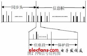
1.PPM modulated signal
PPM modulation uses an optical pulse as the carrier, and the information of the source controls the position of the pulse. The PPM signal structure is shown in Figure 1.
2. Implementation of PPM modulation system
2.1 Hardware Design
The PPM hardware design block diagram is shown in Figure 2.

PPM modulation can be achieved by designing a DSP minimum system plus FLASH for program storage. DSP chip adopts TMS320C5410, the internal RAM space is large, the general application does not need external expansion RAM, the working clock is 100MHz, six-stage pipeline, is a general-purpose high-speed low-power digital signal processing chip, and the peripheral (I/O) working voltage is 3.3. V, the nuclear working voltage is 2.5V, and the ground is digital ground. The power circuit uses the power chip TPS73HD325. The typical input voltage is +5V, which provides +3.3V and +2.5V power output for the VC5410. The TPS73HD325 specific circuit connection can be found on the TI website, and a reset can also be provided. The JTAG port should be connected to some pull-up resistors so that it can be connected to the emulator. Also note that some unused pins of the DSP should also be connected to pull-up resistors. The function of the external FLASH is to load the PPM modulation code into the emulator and the PC, and power the system separately to implement PPM modulation. FLASH adopts SST39VF400, and its usage method can refer to the manual of SST39VF400 on TI. Due to space limitations, there is not much to introduce here. Finally, an LED is connected to the XF pin of the DSP as an output indication of the modulation signal.
2.2 Software Design
The system is designed to be 256PPM, sending a piece of information, including 5 sync headers, 60 messages, and an information value of 65. The laser pulse repetition frequency is 50 Hz, and the interval between adjacent two pulses is required to be greater than 20 ms. Here, the time slot interval is 40 μ s, and the number of protection slots is set to 512, which meets the requirements. The DSP timer is used to generate a 40μs timing, which results in an accurate 40μs pulse width. First define several counters. The sync header interval is set to 512, counted by t0; the number of sync headers is set to 5, counted by t1; t2 represents the value added by the information and guard slot 512; the number of information is set to 60, denoted by t3. The software flow diagram includes a main program flow chart and an interrupt service program flow chart. The interrupt service program flow is shown in Figure 3.
The main program flow chart includes initialization t0, t1, t3, defines t3 information to be sent, sets the timer interrupt for 40μs, opens the interrupt, and waits for the interrupt. When the time is up, enter the interrupt and execute the interrupt service routine.
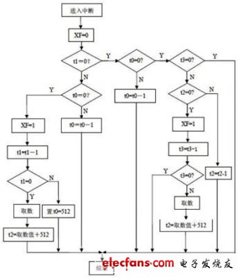
Figure 3 interrupt service program flow chart
3 Test results The results of the 256PPM modulation test observed with a digital oscilloscope are shown in Figure 4. Each cell represents 10ms and is approximately 256 slot widths. In the figure, the first and second lines are synchronous time slots, with an interval of 512 × 40 μ s = 20.48 ms, which is about two squares, which is consistent with the theory; the last three are information time slots, which are equal to the previous one, two squares. More, it is also consistent with the theoretical interval (512 + 65) × 40μ s of information slots.

Figure 4 256PPM modulation test results
Conclusion:
Based on the PPM signal structure, the hardware implementation platform is built. At the same time, the modulation is realized in the CCS2.0 environment. The test results are in line with the theory. It has been successfully used in the PPM modulation and demodulation system design of the author. Part of the implementation. Innovation: A scheme for implementing 256PPM modulation with DSP, including hardware circuit design and software design, is simple and practical, and is suitable for PPM modulation with arbitrary number of slots and arbitrary pulse width.
008615081129555 south africa candles market is very big market .and 68g 65g 58g candles 6x25 packing are popular .
the white color candles made of 100% paraffin wax ,color is pure white .very strong .we aslo supply color candles .red yellow green blue .black color candles .you can choose .
welcome to visit my factory .
any candles inquire pls be free to contact with Me /ANGEL
South Africa Market Candle,South Africa Fluted Candle,South Africa White Candle,Africa Stick Fluted Candle
Shijiazhuang Zhongya Candle Co,. Ltd. , https://www.zycandlefactory.com