introduction
LED lighting is the mainstream of global energy conservation, and high-power LED lighting is the mainstream trend of the world's lighting system. High-power LED features high brightness, energy saving, safety and stability, saving 60% ~ 70% compared with traditional light sources.
The traditional sound and light control delay controller can achieve good control of the lamp. When the light is dark or at night, it can effectively realize that "the person lights up and the person goes to the light", but because the switch is used A mechanical controller such as a relay, so it is more likely to be damaged due to frequent switching in places with a large flow of people.
According to the existing high-power LED spotlight products on the market, intelligent lighting systems can be designed for use in corridors, stairs, classrooms and other places.
The system is powered by a 24 V / 3 A switching power supply, and the lower stage can distribute multiple LED intelligent lighting modules (see Figure 1). The controller adopts AT89C2051, and the constant current drive adopts PT4115 chip. The lighting and brightness of the lamp are realized and changed by dimming.
The DIM terminal of the PT4115 chip can be adjusted by PWM dimming from 0 to 100%. According to this feature, an intelligent dimming module integrating sound control, light control and time control is designed. Its functions are:
(1) When there is light (natural light), the light does not illuminate with or without sound.
(2) When there is no light (natural light), if someone produces a sound, the controller first determines the time period. If the sky is completely dark (defined as the first time period), the LED emits 100% brightness. In the remaining time period, the sky is still brighter, and the controller can output a 50% duty cycle square wave to make the LED emit 50% brightness, which can further save power and improve power efficiency.
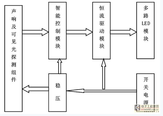
Figure 1 LED intelligent drive system block diagram
1 PT4115 based constant current drive
1. 1 Introduction to PT4115 chip
PT4115 is a continuous inductor current conduction mode buck constant current source for driving one or more series LEDs. PT4115 input voltage range is 6 V ~ 30 V, output current is adjustable, up to 1. 2A Depending on the input voltage and external components, the PT4115 can drive up to tens of watts of LEDs. The PT4115 has a built-in power switch that uses high-side current sampling to set the average LED current and accepts analog dimming and a wide range through the D IM pin. PWM dimming. When the voltage of D IM is lower than 0.3 V, the power switch is turned off, and the PT4115 enters a standby state of extremely low operating current.
1. 2 LED spotlight drive circuit
When V IN is powered up, the initial current of the inductor ( L ) and current sense resistor ( RS ) is zero and the LED output current is also zero (see Figure 2). At this time, the internal power switch is turned on and the potential of SW is low. Current flows from V IN to ground through inductor (L), current sense resistor (RS), LED, and internal power switch. The slope of current rise is determined by V IN , inductor (L ), and LED drop, producing a voltage across RS. Poor VCSN, when (V IN-VCSN ) > 115 mV, the internal power switch is turned off, and the current flows through the inductor (L), current sampling resistor (RS), LED and Schottky diode (D) with another slope; When ( V IN-VCSN ) < 85mV, the power switch is turned back on, so that the average current on the LED is IOUT = (0. 085+ 0. 015) /2 ?RS = 0. 1 /R S. If not Using the dimming function, the DIM pin can be left floating and the set maximum current can be output.

Figure 2 LED spotlight drive circuit
2 Top249Y based 72W switching power adapter design
2. 1 Transformer design
High-frequency transformer design should pay attention to: 1) In the design of high-frequency transformer, the magnetic induction in the core should not be saturated at the maximum output power, so as to avoid distortion in large signals. 2) During the transient process, the leakage inductance and distributed capacitance of the high-frequency chain will cause surge current and spike voltage and pulse top oscillation, which will increase the loss and cause damage to the switch tube in severe cases. At the same time, when the number of turns of the output winding is large and the number of layers is large, the influence of the distributed capacitance should be considered, and reducing the distributed capacitance is beneficial to suppress the interference of the high-frequency signal on the load. It is difficult to reduce the distributed capacitance and leakage inductance at the same time for the same high-frequency transformer. The proper capacitance and inductance should be ensured according to different working requirements.
2. 2 switching power supply circuit
In Figure 3, C 6 is an X-type capacitor that filters out the series-mode interference between the grids. L2 is a common mode suppressor that filters out common mode interference and C 1 is the input filter capacitor. R 11 uses a 2MΩ resistor value for undervoltage and overvoltage detection, while providing voltage feedforward that reduces the output voltage frequency ripple.
TOP249Y The DC voltage range in this circuit is 100~450 V. Once this voltage range is exceeded, TOP249Y will automatically turn off. Resistor R 10 uses a 20.5 K resistance value to externally set the current limit to be slightly higher than the full load peak current at low voltage operation, allowing the use of a smaller transformer core while avoiding startup and output load transients The core is saturated. VR1 is the instantaneous voltage suppression tube, the model is P6KE200, and capacitor C 11 is connected in parallel to reduce the loss of Zener clamp. D1 is the blocking diode type. UF4006 is optional. The target clamp voltage average is about 180 VR 4, R 5, R 6 are the sampling resistance of the output voltage. After sampling, it is compared with the internal reference voltage of TL431 to generate the error voltage. The output voltage is stabilized by the PC817A optocoupler feeding back to control pin C, which in turn changes the output duty cycle of TOP249Y.
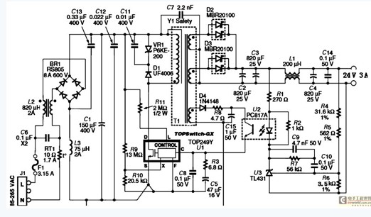
Figure 3 72W Switching Power Adapter
3 Intelligent controller based on AT89C2051
The intelligent controller circuit based on AT89C2051 is shown in Figure 4. It is mainly composed of sensor unit, A \D conversion unit and controller unit. The AT89C2051 chip is used to process the signal data after the signal from the voice and light sensor is shaped to control the LED driver. In this circuit, the p3. 0 and p3. 1 ports of the AT89C2051 are used for input signal detection, and the remaining 13 ports are selectable for output control. The software flow chart is shown in Figure 5.
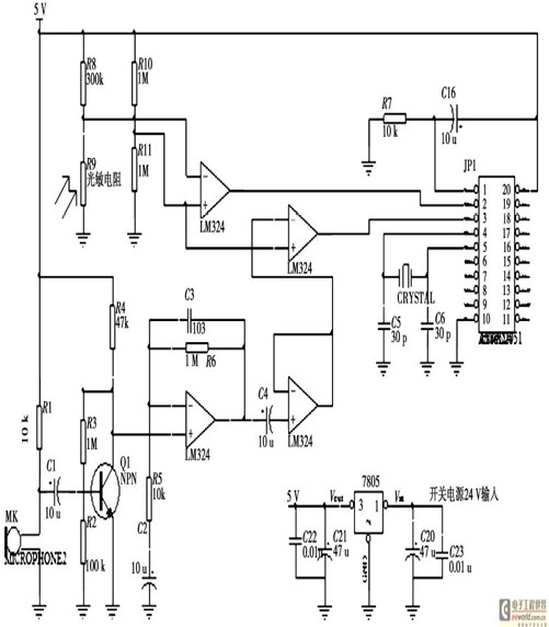
Figure 4 intelligent controller circuit diagram
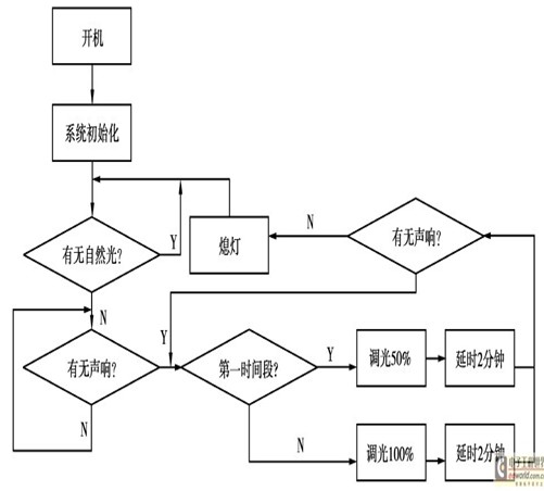
Figure 5 software flow chart
4 Summary
The LED spotlight intelligent driving system designed by the author can effectively monitor and detect changes in the surrounding environment, and turn off and turn on the light source and dimming in time. Compared with the traditional sound and light control delay switch lighting system, the system not only saves a lot of energy, but also greatly improves the electrical efficiency of its unique dimming module. The system has a good application prospect in engineering.
Prototype PCB Assembly = Prototype Printed Circuit Board Assembly, which means the PCB Board quantity is not many and could be taken as prototype job. Normally, Prototype PCB assembly job will be done all by hand, or the small parts by machine and big parts by hand, or all parts by machine. After all parts placed on the PCB board, then it will go through re-flow soldering process. Zhongfeng would manufacture the prototype PCB boards follow the design file, source the components follow the BOM file and do the PCB Assembly job follow the assembly drawing and the pick&place file. After PCB assembly done, the components would be mounted on the PCB boards tightly and connected each other through the copper circuits. We call such board as PCBA board or prototype PCBA board.
Depends on the components assembly types, it have THT PCB assembly, SMT PCB Assembly , one sided SMT and THT PCB assembly, two sided SMT and THT PCB assembly.
Depends on the PCB type, it have Rigid PCB Assembly, Flex PCB Assembly and Flex-Rigid PCB Assembly.
Also we would call some PCB assembly types as Prototype PCB assembly, Mass PCB Assembly , Turnkey PCB Assembly, LED PCB Assembly and BGA PCB Assembly , etc.
With our 15years professional experience, we are available for all types of PCB assembly service from prototype to mass production, available for 01005, 0201, 0.3mm BGA, 0.3mm QFP.
PCB Assembly Capabilities
|
Quantity |
1 pcs - 1,000,000 pcs |
|
Assembly type |
SMT, THT or Hybrid |
|
Parts procurement |
Full turnkey (ZhongFeng provide all components) |
|
Partial turnkey ( Customer provide the main components and ZhongFeng provide the rest) |
|
|
Kitted (Customer provide all components) |
|
|
Component types |
SMT 01005, 0201, BGA 0.3mm pitch, QFP 0.3mm pitch, etc. |
|
Test |
Visual Inspection, AOI, Custom testing, ICT, FCT, Test jig |
PCB Assembly Products Show

PCB SMT Assembly Factory Show


Prototype PCB Assembly
Prototype PCB Assembly,Quick Turn Prototype PCB Assembly,Prototype PCB Assembly Service,PCB Prototype Board Assembly
ZhongFeng Electronic Technology Co., Limited , https://www.dopcba.com