Global mobile data consumption increased by 2.6 times in 2010. This is a three-fold increase in mobile data usage for three consecutive years. By 2015, global mobile data traffic is expected to grow to 26 times in 2010. One of the key factors driving this dramatic growth is the rapid adoption of smartphones and tablets. Global mobile data users want their devices to be connected to the world at high speed anywhere in the world.
This expectation puts a huge burden on network and device performance. In mobile data devices, the antenna is the only component of the "contact" network, and optimizing antenna performance is becoming increasingly important. However, the challenges of 4G antenna design in smartphones and tablets are daunting. While there are many viable solutions to these challenges, each has a potential performance compromise.
4G antenna design challenge
There are many factors that can affect the antenna performance of handheld mobile communication devices. Although these factors are related, they can usually be divided into three categories: antenna size, mutual coupling between multiple antennas, and device usage models.
Antenna Size Antenna size depends on three factors: operating bandwidth, operating frequency, and radiation efficiency. Today's bandwidth requirements are increasing, driven by FCC frequency allocations in the US and carrier roaming agreements worldwide; different regions use different frequency bands. "Bandwidth and antenna size are directly related" and "efficiency and antenna size are directly related" - this usually means that larger sized antennas can provide greater bandwidth and higher efficiency.
In addition to bandwidth, the antenna size also depends on the operating frequency. In North America, operators of Verizon Wireless and AT&T Mobility chose to promote LTE products in the 700MHz band, which was part of the FCC UHF-TV redistribution band a few years ago. These new bands (17,704-746MHz and 13,746-786MHz) are lower than the traditional cellular bands used in North America (5,824-894MHz). This change is huge because the lower the frequency, the longer the wavelength, and the longer the antenna is needed to maintain the radiation efficiency. In order to ensure radiation efficiency, the antenna size must be made large. However, device system designers also need to add larger displays and more features, so the available antenna length and overall size are greatly limited, reducing antenna bandwidth and efficiency.
The high-speed wireless protocol for mutual coupling between antennas requires the use of MIMO (Multiple Input Multiple Output) antennas. MIMO requires multiple antennas (usually two) to operate at the same frequency at the same time. Therefore, multiple antennas need to be placed on the telephone equipment. These antennas must work at the same time and cannot affect each other. When two or more antennas are placed close together, a phenomenon called mutual coupling occurs.
For example, two antennas are placed next to the mobile platform. A portion of the energy radiated from the antenna 1 will be intercepted by the antenna 2, and the intercepted energy will be lost in the terminal of the antenna 2 and cannot be utilized, which can be expressed by the loss of the system power added efficiency (PAE). According to the principle of interchangeability, this effect is the same in the transmit and receive modes. The coupling amplitude is inversely proportional to the separation distance of the antenna. For handset implementations, the distance between antennas operating in the same frequency band in MIMO and diversity applications can be 1/10 wavelength or less. For example, the free space wavelength at 750 MHz is 400 mm. When the interval is small, such as much less than one wavelength, the degree of coupling will be high. The energy coupled between the antennas is useless and only reduces data throughput and battery life.
The device usage model has a large change in the usage model of smartphones and tablets compared to traditional mobile phones. In addition to normal operation, these devices also meet electromagnetic wave energy absorption ratio (SAR) and hearing aid compatibility (HAC) regulations.
Another aspect of using models is the type of consumer content. Video-intensive mobile applications such as massively multiplayer online role-playing games (MMORPGs) and live video data streams continue to drive data usage up. According to ABI Research, from 2009 to 2015, data usage in Western Europe and North America is expected to grow at a compound annual growth rate (CAGR) of 42% and 55%, respectively. These similar applications are driving manufacturers to produce larger, higher resolution displays. The increase in data usage is also quietly changing the way consumers hold these devices. For example, for gaming applications, the user must hold both ends of the device with both hands, while other applications may not need to hold the device at all.
Increasingly large display screens and changes in the way the user grips make it increasingly difficult to find a good location for the antenna radiating element that is not blocked by the display or the user's palm. In addition to these constraints, equipment manufacturers expect the product line to have fewer SKUs (minimum inventory units), and the development of platforms that can work anywhere in the world is a trend in such products.
solution
To be global, smartphones or tablets must work in a variety of frequency bands and protocols. Of course, it is not required to work in all frequency bands and protocols at the same time, so an antenna system that can be adjusted to the target operating frequency band can be developed. Such a state tuned antenna may be referred to as a "smart antenna" or an "adaptive antenna." The basic principle is to limit the instantaneous operating frequency to one or two narrowband bands of interest to meet the protocol requirements of a particular region. In this way, the requirements for broadband operation are reduced, allowing the antenna to be packed into a more compact space without sacrificing radiation efficiency.
There are two basic ways to perform antenna tuning: feed point matching and aperture tuning. However, there are many factors that influence the implementation decisions of these methods, and there is currently no single solution for each application.
Feedpoint matching feedpoint matching can be used in many antenna implementations, whether tunable or not. The main function of the matching circuit is to match the impedance of the antenna termination to the rest of the radio system (usually 50 Ω) over a wide range of operating conditions. A typical tunable matching implementation uses parallel or series variable capacitors as part of the impedance matching circuit. Adjusting the capacitance can change the resonant frequency of the target circuit.
Compression and tuning ranges depending on the desired antenna size typically require a wide range of capacity variations to achieve frequency migration, thus requiring multiple tuning elements and/or a wide range of tuning values. Figure 1 shows an antenna feed matching circuit using a variable element.
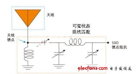
Figure 1: Fixed wideband antenna with variable impedance matching circuit
Aperture tuning aperture tuning is achieved by varying the resonant structure of the radiating element. A typical implementation is to use a simple switch to select different load components on the antenna structure. Switching the load element affects the electrical length of the antenna and thus the resonant frequency. 2 is an AC circuit model of a variable state, aperture tuned antenna employing a fixed impedance matching circuit.
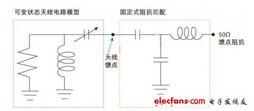
Figure 2: Variable state antenna with fixed feed matching circuit
Whether using feed-point matching or aperture tuning, if the antenna is used for both transmission and reception, the tuning device must be able to withstand the maximum transmit power and maintain good performance characteristics.
Waiting for your phone to charge is a thing of the past, Quick Charger pumps up to 18 W/30W/45W into your compatible smart phone or tablet, reducing charge time by up to 75% compared to conventional charger.
MLF is majored in switches, chargers, adapters and LED and its annual sales amount exceeds 50 million dollars.MLF operates on automatic production line and produces 3 million Power Adapters monthly.
Quick Charger
Rapid Charger,Rapid Charger For Phone,Fast Charger,Fast Charger For Phone
Meile Group Limited , http://www.hkmeile.com