Abstract: This paper presents a DC motor control system that utilizes the TL494 as its central component, combined with PWM (Pulse Width Modulation) technology. The H-bridge-based DC motor control system using TL494 offers a simplified circuit design, strong driving capability, low power consumption, ease of control, and reliable performance. Due to their excellent starting, braking, and speed regulation characteristics, DC motors are widely used in industries, aerospace, and other fields. With the advancement of power electronics, PWM has become a popular method for controlling DC motor speed, offering high accuracy, fast response, wide speed range, and energy efficiency. An H-bridge driver circuit enables four-quadrant operation of the motor, including forward rotation, forward braking, reverse rotation, and reverse braking, making it a key component in modern DC motor servo systems.
1. DC Motor PWM Speed Control Principle
As is well known, the speed of a DC motor can be expressed by the following formula:
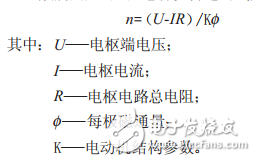
DC motor speed control can be achieved through either field control or armature voltage control. While field control is rarely used, armature voltage control is the most common approach. With the development of power electronics, various methods have been developed to adjust the armature voltage, among which PWM is one of the most widely used techniques. By varying the duty cycle—the ratio of the on-time of the motor's armature voltage to the total period—PWM effectively controls the motor’s speed.
The core of PWM technology is the voltage-to-pulse width converter, which modulates the pulse width based on the control signal. This allows precise control over the on-time of high-power transistors, thereby regulating the voltage applied to the motor’s armature windings.
The structure of the voltage-pulse width converter is shown in Figure 1, consisting of a triangular wave generator, an adder, and a comparator. The triangular wave generator produces a triangular wave UT at a specific frequency. This waveform is added to the input command signal UI by the adder, resulting in a new signal UI + UT, which is then fed into the comparator.
The comparator, typically an operational amplifier operating in open-loop mode, has a very high gain and exhibits switching behavior. A small change in the input difference causes a corresponding switch in the output. Normally, the negative input is grounded, and the signal UI + UT is applied to the positive terminal. When UI + UT is zero, the comparator outputs a full positive level; when UI + UT is positive, it outputs a full negative level.
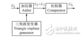
Figure 1: Voltage-Pulse Width Comparator
The modulation process of the signal waveform by the voltage-pulse width converter is illustrated in Figure 2. Due to the comparator’s limiting characteristics, the amplitude of the output signal Us remains constant, while the pulse width varies depending on the command signal UI. The frequency of Us is determined by the frequency of the triangular wave.
When the command signal UI is zero, the output signal Us is a symmetrical rectangular pulse with equal positive and negative widths. As UI increases, the positive pulse width becomes longer than the negative one. Conversely, if UI decreases, the positive pulse width shortens. When UI reaches UTPP/2 (where UTPP is the peak of the triangular wave), the output becomes a continuous positive DC signal. Similarly, when UI is -UTPP/2, the output becomes a continuous negative DC signal.
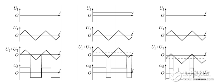
Figure 2: PWM Pulse Width Modulation Waveform
home energy storage,household power storage,home solar power,all in one system
Enershare Tech Company Limited , https://www.enersharepower.com